|
|
|
Categories
|
|
Information
|
|
Featured Product
|
|
|
 |
|
|
There are currently no product reviews.
 ;
Manuale perfetto. Ottimo e utilissimo. Grazie a questo manuale ho potuto realmente risolvere il complesso problema della stampante.
;
Manuale perfetto. Ottimo e utilissimo. Grazie a questo manuale ho potuto realmente risolvere il complesso problema della stampante.
 ;
Was very fast and accurate service. Just what I needed. I recommend to everyone.
;
Very good scan quality, only PC Board scan not enough contrast.
;
First of all I must say that I received the manual in just a few minutes after placing the order. The copy is well done and very readable. I will buy others soon... Thanks, Meyer
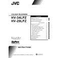
HV- 34LPZ
REMOVING THE CRT
� Replacement of the CRT should be performed by 2 or more pers ons. � After removing the c over, chassis etc., 1. Putting the CRT c hange table on soft cloth, the CRT change table should also be c overed with s uch soft cloth (shown in Fig.3). 2. While keeping the s urfac e of CRT down, mount the TV s et on the CRT change table balanced will as shown in Fig.4. 3. Remove 4 sc rews marked by arrows with a box type screw driver as s hown in Fig.4. � Sinc e the cabinet will drop when screws have been removed, be sure to support the cabinet with hands. 4. After 4 screws have been removed, put the cabinet slowly on cloth (At this time, be carefully so as not to damage the front surfac e of the c abinet) shown in Fig.5. � The CRT should be ass embled according to the opposite sequence of its dismounting steps. � The CRT change table should preferably be smaller that the CRT surfac e, and its height be about 35c m. (Fig.3) � About CRT Spacer (Fig.4) An appropriate CRT spacer should be us ed in the corresponding CRT in acc ordance with the type of the CRT. When a CRT is replaced, special attention should be paid to this matter. CRT CHANGE TABLE
APPROX. 35cm
CLOTH
Fig. 3
Fig. 4
CRT
COATING OF SILICON GREASE FOR ELECTRICAL INSULATION ON THE CRT ANODE CAP SECTION.
� Subsequent to replacement of the CRT and HV transformer or repair of the anode cap, etc. by dismounting them, be sure to coat silic on greas e for electrical insulation as shown in Fig.6. Wipe around the anode button with clean and dry cloth. (Fig.6) Coat silicon grease on the section around the anode button. At this time, take care so that any silicon greas es dose not stick to the anode button. (Fig.7) � Silicon grease product No. KS - 650N CRT Anode button Approx. 20mm (Do not coat grease on this s ection Silic on greas e should be coated by 5mm or more from the outs ide diameter of anode c ap.
CABINET
CRT CHANGE TABLE
Fig. 5
Silic on greas e coating
Anode button (No sticking of silicon grease)
Coating position of silicon grease
Anode cap
Fig. 6
Fig. 7
10
No. 52013
|
|
|
> |
|