|
|
|
Categories
|
|
Information
|
|
Featured Product
|
|
|
 |
|
|
There are currently no product reviews.
 ;
Yes thank you i got the file i was after. There was a slight problem in my communication but it all worked out well.
A job well done.
 ;
Great manual...really saved me. The only problem is that I thought I would be able to download it directly when I paid for it but never received the download instructions until the next morning. The board trace pages were somewhat light also: really need to turn up the contrast on the printer before printing them. The schematic page was great; very clear! Well worth the money.
;
I've been in the electronic business for a long time. I used to buy Sam's Photofact for my needs which intailed having to go to the store and paying about $20 for a package of 3 different units so I was forced to buy more than I needed just to get one.
Owner manual is just at your keyboard and the information is almost instantansouly and the cost is very reasonable. Easy to print out if needed or simply read off of the screen. The larger the screen the better for obvious reasons.
;
Very good manual, at a very good price. Received in a timely manner
;
Only thу cover has poor quality, internal material has excellent quality - exactly what I needed
Thanks!
HV-34LZ
REMOVING THE CRT
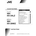
� Replacement of the CRT should be performed by 2 or more persons. � After removing the cover, chassis etc., 1. Putting the CRT change table on soft cloth, the CRT change table should also be covered with such soft cloth (shown in Fig.3). 2. While keeping the surface of CRT down, mount the TV set on the CRT change table balanced will as shown in Fig.4. 3. Remove 4 screws marked by arrows with a box type screw driver as shown in Fig.4. � Since the cabinet will drop when screws have been removed, be sure to support the cabinet with hands. 4. After 4 screws have been removed, put the cabinet slowly on cloth (At this time, be carefully so as not to damage the front surface of the cabinet) shown in Fig.5. � The CRT should be assembled according to the opposite sequence of its dismounting steps. � The CRT change table should preferably be smaller that the CRT surface, and its height be about 35cm. (Fig.3) � About CRT Spacer (Fig.4) An appropriate CRT spacer should be used in the corresponding CRT in accordance with the type of the CRT. When a CRT is replaced, special attention should be paid to this matter. CRT CHANGE TABLE
APPROX. 35cm
CLOTH
Fig. 3
Fig. 4
CRT
COATING OF SILICON GREASE FOR ELECTRICAL INSULATION ON THE CRT ANODE CAP SECTION.
� Subsequent to replacement of the CRT and HV transformer or repair of the anode cap, etc. by dismounting them, be sure to coat silicon grease for electrical insulation as shown in Fig.6. Wipe around the anode button with clean and dry cloth. (Fig.6) Coat silicon grease on the section around the anode button. At this time, take care so that any silicon greases dose not stick to the anode button. (Fig.7)
CABINET
CRT CHANGE TABLE
Fig. 5
� Silicon grease product No. KS - 650N CRT Anode button Approx. 20mm (Do not coat grease on this section Silicon grease should be coated by 5mm or more from the outside diameter of anode cap.
Silicon grease coating
Anode button (No sticking of silicon grease)
Coating position of silicon grease
Anode cap
Fig. 6
Fig. 7
10
No. 52020
 $4.99 HV-34LZ JVC
Owner's Manual Complete owner's manual in digital format. The manual will be available for download as PDF file aft…
|
|
|
> |
|