|
|
|
Categories
|
|
Information
|
|
Featured Product
|
|
|
 |
|
|
There are currently no product reviews.
 ;
The manual is very good quality. very good graphics. complete
;
Excellent printing quality.
A complete and very usefull service manual with all details.
GREAT SERVICE AT VERY LOW PRICE!
A+++++++++++++++++++++++++
;
Excellent, very professional, fast, reliable, congratulations thank you.
;
Excellent printing quality.
A complete and very usefull service manual with all details.
GREAT SERVICE AT VERY LOW PRICE!
A+++++++++++++++++++++++++
;
Excellent printing quality.
A complete and very usefull service manual with all details.
GREAT SERVICE AT VERY LOW PRICE!
A+++++++++++++++++++++++++
HV-34LZ
REMOVING THE CRT
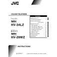
� Replacement of the CRT should be performed by 2 or more persons. � After removing the cover, chassis etc., 1. Putting the CRT change table on soft cloth, the CRT change table should also be covered with such soft cloth (shown in Fig.3). 2. While keeping the surface of CRT down, mount the TV set on the CRT change table balanced will as shown in Fig.4. 3. Remove 4 screws marked by arrows with a box type screw driver as shown in Fig.4. � Since the cabinet will drop when screws have been removed, be sure to support the cabinet with hands. 4. After 4 screws have been removed, put the cabinet slowly on cloth (At this time, be carefully so as not to damage the front surface of the cabinet) shown in Fig.5. � The CRT should be assembled according to the opposite sequence of its dismounting steps. � The CRT change table should preferably be smaller that the CRT surface, and its height be about 35cm. (Fig.3) � About CRT Spacer (Fig.4) An appropriate CRT spacer should be used in the corresponding CRT in accordance with the type of the CRT. When a CRT is replaced, special attention should be paid to this matter. CRT CHANGE TABLE
APPROX. 35cm
CLOTH
Fig. 3
Fig. 4
CRT
COATING OF SILICON GREASE FOR ELECTRICAL INSULATION ON THE CRT ANODE CAP SECTION.
� Subsequent to replacement of the CRT and HV transformer or repair of the anode cap, etc. by dismounting them, be sure to coat silicon grease for electrical insulation as shown in Fig.6. Wipe around the anode button with clean and dry cloth. (Fig.6) Coat silicon grease on the section around the anode button. At this time, take care so that any silicon greases dose not stick to the anode button. (Fig.7)
CABINET
CRT CHANGE TABLE
Fig. 5
� Silicon grease product No. KS - 650N CRT Anode button Approx. 20mm (Do not coat grease on this section Silicon grease should be coated by 5mm or more from the outside diameter of anode cap.
Silicon grease coating
Anode button (No sticking of silicon grease)
Coating position of silicon grease
Anode cap
Fig. 6
Fig. 7
10
No. 52020
|
|
|
> |
|