|
|
|
Categories
|
|
Information
|
|
Featured Product
|
|
|
 |
|
|
There are currently no product reviews.
 ;
Great tape deck manual!
I'm very positively surprised, because it is a very long manual, lot of pages, drawings, diagrams, description of how to make the alignment and adjustment procedures.
It is as good as the old "Naka" manuals from the 1970's - if somebody have seen them, they know what I mean by that.
I recommend to buy this very much !
;
I am a vintage hifi collector. No way to fix that device without the appropriate service manual...thanks to your site I got it and every thing is easier now. I got the manual right after ordering: fast cheap accurate ... thank you
;
Wonderful job clear. Qick fantastic. These people are really good. If even a problem arise they are wonderful assisting you. These scheme is so net despite this is a very old TV. Thank you for everything!!!!!!!!
;
Detailed schematic diagram, manual for professionals
;
Good service manual,exploded view,adjusment and test point locations,head alignment,mechanical checks and adjusments,all perfect.
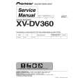
DECK MECHANISM DISASSEMBLY
(D)
Opener Lid
(Fig. A-5-3)
(C)
Spring Arm T/Up Arm Assembly T/up
(Fig. A-5-4)
Arm Assembly Pinch
Base Assembly P4 Support CST
(Fig. A-5-5)
(Fig. A-5-1)
(A)
(B)
(Fig. A-5-2)
Fig. A-5 15. Support CST (Fig. A-5-1)
1) Break away the (A) part shown above Fig. A-5-1 from the Embossing of the Chassis in the clockwise direction, and lift up the Support CST. 2) Lift up the Arm Assembly T/up.
NOTE
(1) When reassembling, unhook the Spring Arm T/up Shown above (No.17.1) to the original position.
Opener Lid
16. Base Assembly P4 (Fig. A-5-2)
1) Break away the (B) part shown above Fig. A-5-2 from the Embossing of the Chassis in the counterclockwise direction and lift up the Base Assembly P4.
17. Opener Lid (Fig. A-5-3)
1) Hook the Spring Arm T/up on the Split digged under the Arm Assembly T/up.(Refer to Fig.A-5-4(D)). 2) Break away the (C) Part of the Opener Lid from the Embossing of the Chassis in the Clockwise direction and lift up the Opener Lid.
Spring Arm T/up
Arm Assembly T/up
18. Arm Assembly T/up (Fig. A-5-4)
1) Confirm that the Spring Arm T/up is placed as above (No.17.1).
19. Arm Assembly Pinch (Fig. A-5-5)
1) Lift up the Arm Assembly Pinch.
54
|
|
|
> |
|