|
|
|
Categories
|
|
Information
|
|
Featured Product
|
|
|
 |
|
|
There are currently no product reviews.
 ;
The purchased manual is an high-quality scan of the original JVC paper-based Owner´s Manual. I am very satisfied!
;
Very satisfied with received document, all is right, Thank You very much, it was a Pleasure to work with You.
 ;
great site, the most easy and fastest way to find the manual you need, no 5 star because the manual was only available in german, but I speak german as well so no problem for me.
;
thanks for this download i got a pioneer bdp-lx70a blu-ray player and it had no manual i search everywhere on the internet and came across owner-manuals.com and i found that it was so easy to find and downloaded from this site if i ever need a manual again this would be the first place that i would come too thanks guys
;
Superb! It's the original manual. We can now use our old calculator with its full function.
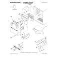
1-3-11. Band Adjuster, S Reel Table Assy and TG2 Arm Block Assy 1. Removal procedure 1) Remove the screw (special head screw M1.4 � 2.5) 1. 2) Remove the band A of the TG2 arm block and remove the band adjuster 2. 3) Remove the S reel table assy 3. 4) Remove the tension spring (tension regulator spring) 4. 5) Remove the TG2 arm block assy 5. 2. Attachment procedure 1) Install the S reel table assy 3. 2) Apply grease in the TG2 arm pivot shaft B. Amount of grease: a ball of 1.0 mm diameter of grease Re-application of grease to the point which is greased already before is not necessary. 3) Hold the TG2 arm block assy 5 with tweezers and insert it in the TG2 arm pivot shaft B. 4) Hook the tension spring (tension regulator spring) 4 on the TG2 arm block 5 with tweezers so that the hook faces downward. 5) Hook the tension spring (tension regulator spring) 4 on the LS chassis block assy (the third hook from the rear end). 6) Hook the A portion of the band on the claw of the band adjuster 2. 7) Hold the band adjuster with tweezers as shown in C. Insert the band into groove of the S reel table assy while rotating it, and insert the adjuster�s dowel into the dowel hole D of the LS chassis block assy. 8) Install the band adjuster 2 with the screw (special head screw M1.4 � 2.5) 1. Tightening torque: 0.059 ± 0.01N�m (0.6 ± 0.1kgf�cm) 9) Perform the TG2 FWD Position Adjustment referring to section 1-4-1. 10) Perform the FWD Back-tension Adjustment referring to section 1-4-4. 11) Perform the Reel Torque Check referring to section 1-4-2.
4 Tension spring (Tension regulator)
3 S reel table assy
1 Screw (M1.4 � 2.5) 2 Band adjustor
The spring hook faces downward. TG2 arm 5 block assy
A C
Dowel D Hole D Band
Shaft B
Key Points in Re-assembling
Third from the rear end The spring hook faces downward.
Apply Grease Points to be noted
During installation, apply grease in the TG2 arm pivot shaft hole. Amount of grease: a ball of grease of 1.0 mm diameter Re-application of grease to the point which is greased already before is not necessary. B
HVR-M10C/M10E/M10J/M10N/M10P/M10U 6-21
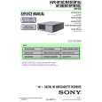 $4.99 HVRM10E SONY
Service Manual Complete service manual in digital format (PDF File). Service manuals usually contains circuit diagr…
|
|
|
> |
|