|
|
|
Categories
|
|
Information
|
|
Featured Product
|
|
|
 |
|
|
There are currently no product reviews.
 ;
Thanks you very much for this "hard to find" service manual.
Will help a lot in repairing this receiver.
;
Thanks you very much for this "hard to find" service manual.
Will help a lot in repairing this receiver.
;
Thanks you very much for this "hard to find" service manual.
Will help a lot in repairing this receiver.
;
Thanks you very much for this "hard to find" service manual.
Will help a lot in repairing this receiver.
;
Thanks you very much for this "hard to find" service manual.
Will help a lot in repairing this tuner.
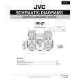
HX-Z1 3.1.2 Removing the CD tray assembly (See Fig.2~9) (1) Remove the front panel assembly. (2) Remove the CD changer mechanism assembly. (3) Remove the CD Servo control board. (4) Remove the screw B' retaining the lod stopper. (5) From the T.bracket section "b" and clamper base section "c" , remove both of the edges fixing the rod(See Fig.2 and 3). (6) Remove the screw B retaining the disc stopper (See Fig.3). (7) Remove the three screws C retaining the T.bracket (See Fig.3). (8) Remove the screw D retaining the clamper assembly (See Fig.3). (9) From the left side face of the chassis assembly, remove the one screw E retaining both of the return spring and lock lever(See Fig. 4). (10) By removing the pawl at the section d fixing the return spring, dismount the return spring(See Fig.4). (11) Remove the three lock levers(See Fig.4). (12) Check whether the lifter unit stopper has been caught into the hole at the section e of CD tray assembly as shown in Fig.5. (13) Make sure that the driver unit elevator is positioned as shown in Fig.6 from to the second or fifth hole on the left side face of the CD changer mechanism assembly. [Caution] In case the driver unit elevator is not at above position, set the elevator to the position as shown in Fig.7 by manually turning the pulley gear as shown in Fig.8. (14) Manually turn the motor pulley in the clockwise direction until the lifter unit stopper is lowered from the section e of CD tray assembly(See Fig.8). (15) Pull out all of the three stages of CD tray assembly in the arrow direction f until these stages stop (See Fig.9). (16) At the position where the CD tray assembly has stopped, pull out the CD tray assembly while pressing the two pawls g and g' on the back side of CD tray assembly(See Fig.9). In this case, it is easy to pull out the assembly when it is pulled out first from the stage CD tray assembly.
Fig.2
Fig.3
Fig.4
16
 $4.99 HX-Z1 JVC
Circuit Diagrams Set of circuit diagrams. The diagrams will be provided as PDF file. The file will be delivered after… 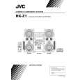 $4.99 HX-Z1 JVC
Owner's Manual Complete owner's manual in digital format. The manual will be available for download as PDF file aft…  $4.99 HX-Z1 JVC
Parts Catalog Parts Catalog only. It's available in PDF format. Useful, if Your equipment is broken and You need t…
|
|
|
> |
|