|
There are currently no product reviews.
 ;
Absolutely top, I've got now all Service-Manuals I'll need to repair my Mackie-Mixer!
;
The service manuel is very helpful, we where able to restore the device to its working operation again.
;
Great quality complete service manual!!! complete parts list and drawings
;
Again a great job. I never been disilluted from them! Clear scheme, complete and very good for repairing!
;
Great manual just what I needed, great service as always, thanks.
HX-Z3 Removing assembly the power transformer (See Fig.28, 29)
Power transformer assembly
Prior to performing the following procedure, remove the metal cover, the CD changer mechanism assembly, the rear panel, the main board and the bridge board / regulator board. 1. Remove the screw N attaching the primary board. 2. Disconnect the wire from connector CN231 and CN232 on the primary board.
N
3. Remove the four screws O transformer assembly. attaching the power Fig.28
Primary board
4. Cut the tie band and detach power cord from primary board. REFERENCE: When disconnecting the power cord from connector CN250 on the primary board, remove the fixing band.
Primary board CN231, CN232 Power transformer assembly CN250
O
Fixing band
<Front panel assembly>
Prior to performing the following procedure, remove the metal cover, the CD changer mechanism assembly and the front panel assembly.
O
Fig.29
Cord stopper
Removing assembly
the
cassette
mechanism (See Fig.30)
Head amplifier & mechanism control board CN33 Band
1. Disconnect the card wire from connector CN33 on the head amplifier & mechanism control board. 2. Remove the two screws P, and the two screws Q attaching the cassette mechanism assembly. 3. Cut the band.
P
Q
Removing the headphone board (See Fig.30)
1. Remove the screw Q attaching the wire extending from the headphone board. 2. Remove the screw R and pull out the headphone board backward.
Cassette mechanism assembly
QR
Headphone board
Fig.30
1-13
 $4.99 HX-Z3 JVC
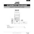
Circuit Diagrams Set of circuit diagrams. The diagrams will be provided as PDF file. The file will be delivered after… 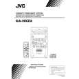 $4.99 HX-Z3 JVC
Owner's Manual Complete owner's manual in digital format. The manual will be available for download as PDF file aft… 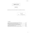 $4.99 HX-Z3 JVC
Parts Catalog Parts Catalog only. It's available in PDF format. Useful, if Your equipment is broken and You need t…
|