|
|
|
Categories
|
|
Information
|
|
Featured Product
|
|
|
 |
|
|
There are currently no product reviews.
 ;
Very fast, clear and usefull site !
Also this Service Manual are very well maked and with a very good definition !
Very fast download speed !
Recomended Seller !
;
The manual you sent me was excellent. It included clear, readable diagrams and a usable parts list. I would surely use your service again. Thanks
;
Payments were processed quickly and items were exactly as described. I will use owner-manuals.com in the future for any other manual needs.
;
The Technics manual was very clear and I was able to solve my technical problems.
I did not think that anyone kept these manuals and was pleasantly surprised to find them on the Internet and at an affordable price.
I would recommend Owner Manuals as a first source of technical products for ‘dated’ equipment manuals.
Ian
;
The content of the manual was not found on the Internet and was a hard find. I check the net for 5 hours until I came across this web-site. When I did find the book it Auto loaded into my IPAD PDF shelf for books for review at anytime. Overall I am satisfied with the book and it answered all my questions. This repair book is obsolete because the product I bout it for is pretty old. Thanks for the help with the download and even having the manual. Thanks 73's K5HRD
2.4.6 Reattaching the Play/ Record & Clear head (See Fig.11~13) (1) Reattaching the head mount assembly. a) Change front of the direction cover of the head mount assembly to the left (Turn the head forward). b) Fit the bosses O', P', Q', U' and V' on the head mount assembly to the holes P and V, the slots O, U and Q of the mechanism sub assembly (See Fig.11 to 13). CAUTION: To remove the head mount assembly, turn the direction cover to the left to disengage the gear. If the gear can not be disengaged easily, push up the boss Q' slightly and raise the rear side of the head mounts slightly to return the direction lever to the reversing side. (2) Tighten the azimuth screw for reversing. (3) Reattach the spring from the back of the Play/ Record & Clear head. (4) Connect the flexible wire to connector CN31 on the head amplifier & mechanism control board.
O' P' V'
U'
Head mount assembly Fig.11
Head mount assembly
Q'
Direction cover
O PQ V U
Direction cover
Fig.12
Head
Azimuth screw for reversing Head mount
Spring Flexible wire
CN31
Fig.13
Head amplifier & mechanism control board
(No.22041)1-29
 $4.99 HX-Z9V JVC
Owner's Manual Complete owner's manual in digital format. The manual will be available for download as PDF file aft… 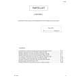 $4.99 HX-Z9V JVC
Parts Catalog Parts Catalog only. It's available in PDF format. Useful, if Your equipment is broken and You need t…
|
|
|
> |
|