|
|
|
Categories
|
|
Information
|
|
Featured Product
|
|
|
 |
|
|
There are currently no product reviews.
 ;
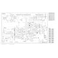
The schematic is very helpful and the images are very good.The schematic is very helpful and the images are very good.The schematic is very helpful and the images are very good.The schematic is very helpful and the images are very good.The schematic is very helpful and the images are very good.The schematic is very helpful and the images are very good.
;
Welcome. The scheme is clearly helped me to repair. Worth to download it.
 ;
Excellent manual, very clear, technical specification provided, useful information regarding adjustment and set up.
;
fast and easy and exactly what I was looking for. Not the cheapest but value for money after all.
;
The manual for the Sansui P-L75 was not one of the more informative turntable manuals around but for $5 it was helpful enough.
ICD-SX25/SX25VTP
3. Sleep test � Pressing the x�B key causes the set to enter the sleep state. � When the HOLD . switch is ON, the LCD is turned off. When OFF, the LCD is turned on. � Press any keys to exit the sleep state.
x�B (with HOLD . OFF status)
SLEEP SLEEP SOON
8. LED test � LEDs (OPR: red and green) are all turned on.
x�B
LED LED ON
LED OFF
x
LED ON (orange)
x�B (with HOLD . ON status) (LCD OFF) any keys
9. USB test � When the menu starts the USB self-check, either presence or absence of the Vbus is judged.
SLEEP IN
(Vbus is present: �ON VBUS�, Vbus is absent: �OFF VBUS�) � The USB driver always works regardless of presence or absence of the USB signal only when Vbus is available during the USB test. At this time, turning on HOLD . causes the set to move to the suspend state. Turning off the Vbus causes the set to return to the test menu. � In the menumode if the Vbus is supplied, any key will not work. Therefore the Vbus will be supplied after surely pressing the x�B key.
Vbus on
VBUS OFF
any keys
4. Beep test � Beep sound of 1.3 kHz or 2 kHz is output.
x�B . > (select), x�B (set)
BEEP BEEP1.3K
x
:
BEEP 2.0K BEEP 1.3K
x�B
USB
HOLD . ON
VBUS ON SUSPEND
Suspend mode
:
on BEEP1.3K
on BEEP 2.0K
x
cut Vbus
cut Vbus
x
x
5. RTC test � Perform the function test of the RTC and EEPROM. (1) RTC EEPROM test Confirmation of writing, reading (verifying) and erasing of arbitrary data with the specified registers. (2) RTC clock function test Confirmation that RTC updates the time to the microcomputer at one second interval. � OK, NG judgement is performed to the test result. When NG, it is displayed which device RTC or EEPROM becomes NG. (All OK : �RTC OK� / RTC NG : �RTC BAD� / EEPROM NG : �EEP BAD�)
x�B
RTC
RTC OK
10. Key durable test � Pressing the x�B key makes the count to �------� and sets test standby status. Once more pressing the x�B key makes the count to �000000� and sets the key durable test. In this mode any key input and slide switch operation are counted and the number is displayed. Turn off the power to exit this mode.
x�B
KEY COUNT KEY-----
x�B
any keys or slide switches operation
KEY 000000 KEY 000001
x
Key durable test
x
6. Key entry test � When the any key is pressed, the entry key and the A/D converted value (hexadecimal) of the two channel keys are displayed. � When the x key is pressed, the A/D value of the key is displayed while the key is depressed. When the key is released, the screen returns to the test menu.
x�B
KEY KEY oFFiFF
11. Menu reset � Pressing the x�B key causes the set to enter the menu initialization standby state. � When the following keys are all entered, the EEPROM initialization (returning setting in the menu and user name to default value) and formatting process (deleting all message files in the flash memory) are executed. At the same time, the WakeUp signal is checked, too.
Check keys: VOL� , VOL+ , A-B
, ERASE ,
x
7. Battery remaining power and DC IN test � The detected A/D value (hexadecimal) of the battery remaining power is displayed. When DC jack is inserted, the battery mark on the LCD is turned off.
x�B
bATT FF
DC jack is inserted
bATT FF bATT C2
DIVIDE , DPC ON , DPC OFF , . , x�B , > , FOLDER , MENU , x , z REC , HOLD . ON , HOLD . OFF , DIRECTNL ON, and DIRECTNL OFF , VOICE UP ON, and VOICE UP OFF
BATT
x
DC jack is extracted
9
|
|
|
> |
|