|
|
|
Categories
|
|
Information
|
|
Featured Product
|
|
|
 |
|
|
There are currently no product reviews.
 ;
It´s very very nice manual with all, what i need. Original in good quality. Very fast business. Very much thanks...
;
Purchased the manual that I was looking for at a great price and could download it easily.. Great service experience and for future purchases I plan to use the site.
Thank you very much
;
Exactly what was needed to assess the product - excellent value and great service
;
A site where discontinualed schematic diagrams and back dated information can be found on discontinued radios tv's and any electronic equipment can be found. Newer manuals either Service and operating manuals. Radio amateurs should find this site a great source for ham radio equipment manuals. I will return to this site should I need information on any electrical equipment. priced easy to download in a PDF format and print pages need to undertake the repair.
;
Quality scan of the original. All the detail necessary to troubleshoot, repair and adjust the unit. I'm sure I will be downloading more manuals in the future as the need arises.
2-3. MAIN BOARD, LED BOARD
4 Removal the solder. 9 BTP 3x10 8 BTP 3x10
qa MAIN board
0 3 chassis 7 claws 6 LED board 5 BTP 2.6x5
1 knob (control) 2 knob (band)
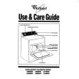
2-4. SETTING THE POINTER
� Setting the Pointer 1. Turn the Knob (Tuning) in the direction of A until it is stopped. 2.Place the rack as shown in the figure. 3.Mount the pointer.
rack (pointer) A
2 pointer 1 rack (pointer)
�5�
|
|
|
> |
|