|
|
|
Categories
|
|
Information
|
|
Featured Product
|
|
|
 |
|
|
There are currently no product reviews.
 ;
It was very usefull, it is clear the quality is super, the price I paid is very afordable.
Generally speaking Iam very happy with this company.
;
The manual was exactly what I needed, Good quality scans too. superb.
;
I am so happy found this site as it consists of so many Manuls and easy to aquire. This onei s exactly what I wanted and much more as it has info on not only how to use the tuner but how to repair it as well. I will come here 1st before purchasing else where! Thanks owner-manual.com!
;
Top class product, I printed it out on A3 paper and it is clear and very easy to follow.
Cheaper than buying a new radio!
;
is part of the manual is very useful for repairing
Here are circuit diagrams
if there is damage, I recommend using this part of the
a complete list of circuit boards and components
ICF-C1200
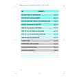
TABLE OF CONTENTS
Specifications ........................................................................... 1 Notes on chip component replacement � Never reuse a disconnected chip component. � Notice that the minus side of a tantalum capacitor may be damaged by heat.
r
1. GENERAL ...................................................................... 2 2. DISASSEMBLY
2-1. Main Board ................................................................. 3
UNLEADED SOLDER
Boards requiring use of unleaded solder are printed with the lead-free mark (LF) indicating the solder contains no lead. (Caution: Some printed circuit boards may not come printed with the lead free mark due to their particular size.)
3. ELECTRICAL ADJUSTMENTS
3-1. Tuner Section .............................................................. 4
4. DIAGRAMS
4-1. Explanation of IC Terminals ....................................... 6 4-2. Block Diagram ............................................................ 7 4-3. Printed Wiring Boards � Main Section (1/2) (Side A) � .................................. 8 4-4. Printed Wiring Boards � Main Section (2/2) (Side B) � .................................. 9 4-5. Schematic Diagram ................................................... 10
: LEAD FREE MARK
Unleaded solder has the following characteristics. � Unleaded solder melts at a temperature about 40°C higher than ordinary solder. Ordinary soldering irons can be used but the iron tip has to be applied to the solder joint for a slightly longer time. Soldering irons using a temperature regulator should be set to about 350°C. Caution: The printed pattern (copper foil) may peel away if the heated tip is applied for too long, so be careful! � Strong viscosity Unleaded solder is more viscous (sticky, less prone to flow) than ordinary solder so use caution not to let solder bridges occur such as on IC pins, etc. � Usable with ordinary solder It is best to use only unleaded solder but unleaded solder may also be added to ordinary solder.
5. EXPLODED VIEWS
5-1. Main Section ............................................................. 13
6. ELECTRICAL PARTS LIST ................................... 14
SECTION 1 GENERAL
LOCATION AND FUNCTION OF CONTROLS
This section is extracted from instruction manual.
2
|
|
|
> |
|