|
|
|
Categories
|
|
Information
|
|
Featured Product
|
|
|
 |
|
|
There are currently no product reviews.
 ;
It`s not your fault tear down is rather incomplete. It doesn`t have complete instructions as to deconstruction for repair.
 ;
THANK YOU FOR A GOOD TRANSACTION, NICE COPY, CLEAR
;
Very Good! All the diagram are easy to read, and its complete.
;
This was an excellent source of detailed assembly information on a device which is at least 12 years old. A very lucky find, coupled with great service.
;
Excellent Service Manual and best price on the Internet. This Service Manual covers everything you could ever need including full circuit schematics, component layout diagrams, stripdown procedure and full parts list/breakdown. I needed this to carry out a modification to one of these headunits and this manual covered everything I needed. Fast delivery, processed within a few hours.
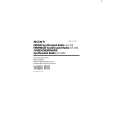
SECTION 3 ELECTRICAL ADJUSTMENTS
0dB=1 µV [FM/TV Section] Setting: BAND switch: FM1 or TV
FM RF SSG 0.01µF set level meter + �
FM FREQUENCY COVERAGE ADJUSTMENT L8 Confirm Adjust for a reading on digital voltmeter. 87.5 MHz (TV 2 ch) 2.3 ± 0.1 V (1.0 ± 0.1 V) 108.0 MHz 8.5 ± 0.5 V (12.5 ± 0.5 V)
Adjustment and Connection Location:
Note: Not use the FM RF signal generator in this adjustment.
[MAIN BOARD] (Component Side)
(
): ICF-S79V
T2 AM IF FM antenna ground (JW17) T1 TV IF (ICF-S79V only) L8 FM FREQUENCY COVERAGE L6 CT4
IC2
FM TRACKING ADJUSTMENT Adjust for a maximum reading on level meter. L6 CT4 87.5 MHz (TV 2 ch (59.75 MHz)) 108.0 MHz
± 22.5 kHz frequency speaker terminal deviation by 400 Hz FM lead wire antenna terminal signal Output level: as low as possible
( ICF-S79L only
): ICF-S79V
[AM (LW/MW) Section] Setting: BAND switch: AM (MW) or LW
Put the lead-wire antenna close to AM RF SSG the set. set 30% amplitude speaker terminal modulation by 400 Hz signal Output level: as low as possible
LW FREQUENCY COVERAGE ADJUSTMENT Adjust for a reading on digital voltmeter. CT5 153 kHz 2.3 ± 0.1 V Confirm 279 kHz 8.5 ± 0.5 V Note: Not use the AM RF signal generator in this adjustment.
L2 TV FREQUENCY COVERAGE (ICF-S79V only) CT1
IC1
level meter + �
ICF-S79L only
LW TRACKING ADJUSTMENT Adjust for a maximum reading on level meter. L5 (LW side) CT2 162 kHz 243 kHz
FM TRACKING
L1
TV TRACKING (ICF-S79V only) FM/TV
L9 AM (MW) FREQUENCY COVERAGE
MW L5 LW
antenna input (JW18)
digital voltmeter MAIN board TP (VT) + �
AM (MW) FREQUENCY COVERAGE ADJUSTMENT Adjust for a reading on digital voltmeter. L9 531 kHz (530 kHz) 2.8 ± 0.1 V
CT5 LW FREQUENCY COVERAGE (ICF-S79L only) L5 CT3
TV antenna ground (JW20)
Repeat the procedures in each adjustment several times, and the frequency coverage and tracking adjustments should be finally done by the trimmer capacitors.
Confirm 1,602 kHz (1,710 kHz) 9.5 ± 0.5 V Note: Not use the AM RF signal generator in this adjustment.
(
AM (MW) TRACKING ADJUSTMENT
): ICF-S79V
AM (MW) TRACKING CT2 L5
ICF-S79V only
TV FREQUENCY COVERAGE ADJUSTMENT Adjust for a reading on digital voltmeter. L2 WEATHER 2 ch 1.0 ± 0.1 V Confirm TV 13 ch 10 ± 0.5 V Note: Not use the FM RF signal generator in this adjustment.
Adjust for a maximum reading on level meter. L5 <MW side> CT3 621 kHz (590 kHz) 1,395 kHz (1,490 kHz)
LW TRACKING (ICF-S79L only)
< (
AM IF ADJUSTMENT
>: ICF-S79L ): ICF-S79V [MAIN BOARD] (Conductor Side)
ICF-S79V only
TV TRACKING ADJUSTMENT Adjust for a maximum reading on level meter. L1 CT1 WEATHER 2 ch (162.40 MHz) TV 13 ch (215.75 MHz)
Adjust for a maximum reading on level meter. T2 455 kHz
ICF-S79V only
TV IF ADJUSTMENT Adjust for a maximum reading on level meter. T1 10.7 MHz
TP (VT)
�5�
�6�
 $4.99 ICF-S79 SONY
Owner's Manual Complete owner's manual in digital format. The manual will be available for download as PDF file aft…
|
|
|
> |
|