|
|
|
Categories
|
|
Information
|
|
Featured Product
|
|
|
 |
|
|
There are currently no product reviews.
 ;
I purchased the unit from a private party and the original owners manual was not available. Having the ability to download it was extremely helpful and clarified operating the equipment immensely. This is a complicated unit and without the manual I would not have been able to maximize it's potential. Thank you.
;
Being a user of older radios of many kinds, preferring them over more modern rigs, this manual was invaluable in the programming of my two. I now know for certain what the assorted buttons functions are, and am very grateful to have found this excellent site. Many thanks for your assistance, Tony.
 ;
Clear and easy to read. All details as expected. Price acceptable , and quick delivery.
;
Quick response and exactly what I was looking for and at a great fair price!
;
5 star quality on these downloadable manuals. Easy to read and all the information is there. A must when doing a custom install or needing to service your precious old school electronics.
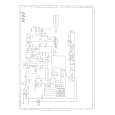
Dubbing (Multi-dubbing)
Do not connect the AC power cord until all other connections have been made. You can dub a video program from VCR 1 to VCR 2 and vice versa.
This shows an example of several possible connections. Also refer to the instruction books of the other components you are using for operation and connection details.
(green) To Component Video Output
(red)
VCR1 (Playback component)
: Signals from VCR 1 to VCR 2
To AUDIO Input To AUDIO Input To S-VIDEO Input
: Signals from VCR 2 to VCR 1
(white)
(red)
To Component Video Input
JX-S333 rear panel
(green) (blue) (red)
(green) (blue) (red)
To AUDIO Input
(white) (white) (red)
TV monitor
(red)
(red)
To S-VIDEO Input
(white) (red)
To S-VIDEO Output
To AUDIO Output
VCR2 (Recording device)
Connection tips � Before making any connections, turn off the power to all components. � It is not required to connect the components using both SVIDEO and component video connectors. To obtain the best possible playback picture on the TV monitor, connect the component using the component video connectors. However, to dub the tapes, it is required to connect the playback components through the S-VIDEO connectors. � If both the S-VIDEO and component video connectors are connected between the components, the incoming signals are emitted through the respective output connectors. (� P. 7 �Video input/output signals�)
(white)
(blue)
(white)
(red)
� The INPUT 1 and INPUT 2 connectors are used for connecting the playback/recording components. Incoming signals from the INPUT 1 and INPUT 2 connectors are emitted through the MONITOR OUT connectors and at the same time... � Signals from the INPUT 1 connectors are emitted through the OUTPUT 2 connectors. � Signals from the INPUT 2 connectors are emitted through the OUTPUT 1 connectors.
12 -EN
|
|
|
> |
|