|
There are currently no product reviews.
 ;
The manual is very good quality. very good graphics. complete
;
Excellent printing quality.
A complete and very usefull service manual with all details.
GREAT SERVICE AT VERY LOW PRICE!
A+++++++++++++++++++++++++
;
Excellent, very professional, fast, reliable, congratulations thank you.
;
Excellent printing quality.
A complete and very usefull service manual with all details.
GREAT SERVICE AT VERY LOW PRICE!
A+++++++++++++++++++++++++
;
Excellent printing quality.
A complete and very usefull service manual with all details.
GREAT SERVICE AT VERY LOW PRICE!
A+++++++++++++++++++++++++
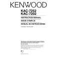
KAC-7202/7252
BLOCK DIAGRAM
ISO AMP L LINE IN L LINE OUT R LINE OUT R LINE IN HPF 50-200Hz BASS BOOST 40-100Hz MUTE SP OUT R MO/ST SENS IC12,16 LPF/OFF/HPF IC1(X08) HPF 50-200Hz IC3(X08) LPF 50-200Hz IC7-9,13,15 BASS BOOST 40-100Hz MUTE SP OUT L POWER AMP Q241,242 Q201-258
IC1 L SP IN R SP IN
REMOTE CONTROL f, GAIN f=40-100Hz GAIN=0-18dB 15V AVR
CONTROL
P-CON
BATT D.D. CON. GND
COMPONENTS DESCRIPTION
� PREAMPLIFIER UNIT (X08-4190-1x)
Ref. No. IC1 IC2 IC3 IC4~6 IC7 HPF Phase reversal amplifier (Lch only) LPF Bass-boost circuit Bass-boost mixing amplifier Application / Function Ref. No. Q101 Q201~204 Q209,210 Q205~208 Q211,213 Q220,222~227,229 Q241,242 Q251~258 Application / Function Remote controller reference voltage Power amplifier initial step differential driving Current limiter Power amplifier second step differential driving Temperature detection for idling Power amplifier final Power amplifier mute Power amplifier driver Power amplifier ATT (-3dB) Power-ON shock preventer circuit P-Con OFF detection Mute drive P-Con control circuit Excess voltage detection Temperature detection control circuit Fan power supply Excess current detection DC detection DC detection for latch For LED control Temperature detection control circuit
� AUDIO UNIT (X09-5830-1x)
Ref. No. IC1,12,16 IC5 IC6 IC7,8 IC9 IC13 IC15 Q1,2 Q3~8 Q9~12 Q13,14 Application / Function Input isolation amplifier DC/DC converter Temperature detection comparator For adjusting bass-boost f For adjusting bass-boost gain Bass-boost phase shifter Bass-boost mixing amplifier ±15V AVR DC/DC converter FET DC/DC converter FET driver For controlling DC/DC converter FET driver
Q280,282 Q601,615~618 Q602 Q603 Q604,605 Q606 Q607,608,619,620 Q609 Q610 Q611,612 Q613,614 Q621,622 Q623
ADJUSTMENT
No. ITEM IDLE CURRENT ALIGNMENT POINT VR1 (Lch) VR2 (Rch) METHOD Connect a DC voltmeter between check land (Refer to PC BOARD) 2.5mV ALIGN FOR NOTE After Power on 5 minutes
1
2
|