|
|
|
Categories
|
|
Information
|
|
Featured Product
|
|
|
 |
|
|
There are currently no product reviews.
 ;
Detailed SONY CFD980 Service Manual at an easy to find one stop shopping. Make my radio hobby technically interesting. Thanks.
 ;
Excellent service from Owner-Manuals.com, good prices and quick turn around. The supplied PDF was good enough quality to be enlarged sufficiently to read component values.
;
Very complete shop manual. It contains everything needed to troubleshoot bascially any problem. Instructions, diagrams, schmeatics, illustrations... it's all there. Highly recommended!
;
Great product, very good quality, found all needed information. Thanks
;
Excellent quality, helped to fix problem. Thank you very much!!!!
KAC-819
CIRCUIT DESCRIPTION
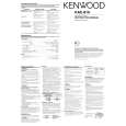
SP P-CON Switching Circuit
When the SP output from the head unit is connected to SP IN, the power can be switched ON/OFF based on the DC voltage of the SP output. However, As certain haed unit models output DC permanently or generate a click during switching OFF, it is required to provide the capability of previous P-CON switching. A circuit which can perform the switching without using a switch is described below. This circuit performs switching by inhibiting the operation of the S-P-CON circuit when a voltage is applied to the P-CON pin.
Circuit operation description
When the head unit is connected to SP-IN, the DC component in the SP output turns Q38 ON through D32 and R158. When a voltage is applied to the P-CON pin under this condition, Q45 is turned ON via R188, positive feedback is applied by combination of Q45 and Q46, Q45 and Q46 are held at ON, so the voltage at point (A) is almost 0V and the SP-P-CON circuit is not activated. This circuit holds the ON status while the DC voltage from SP is present. Therefore, in this condition, the P-CON circuit continues functioning. To cancel the functioning, the voltage at the SP-IN pin should go 0V.
R188 100K
D29
to P-CON terminal 7.5V power control
D32
from SP-P-CON
A
10u35
+
R158
3.3K
Q38
Q46
4.7K
Q45
ADJUSTMENT
No. ITEM INPUT SETTINGS OUTPUT SETTINGS TUNER (RECEIVER) SETTINGS ALIGNMENT POINTS ALIGN FOR FIG.
Connect a cassette receiver or other receiver.
IDEL CURRENT Connect a DC voltmeter to CN3 VR3 After sufficient aging adjust to 2mV
1
-
Volume : 0
-
2
|
|
|
> |
|