|
|
|
Categories
|
|
Information
|
|
Featured Product
|
|
|
 |
|
|
There are currently no product reviews.
 ;
All ok. I pay 5 $ and now i have 92 pages of good scaned service manual for my oooooold akai. Now i will try to repair it.
;
good and ok, very nice , good and ok, very nice, good and ok, very nice
;
Super manual it contains all the things you need to service your Marantz 2100.
;
A very easy to understand and use manual. Well worth the money.
 ;
Very good information with clear drawings. Thanks!
3.2
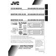
CD mechanism assembly section
� Remove the CD mechanism assembly from the main body. (See "3.1.5 Removing the CD mechanism assembly".) 3.2.1 Removing the mechanism control board (See Fig.1) (1) From the bottom side of the CD mechanism assembly, solder the short sections on the flexible wire. Caution: Solder the short sections on the flexible wire before disconnecting the flexible wire from the connector CN601 on the mechanism control board. If you do not follow this instruction, the CD pickup may be damaged. (2) Disconnect the flexible wire from the connector CN601 on the mechanism control board. (3) Disconnect the flexible wire from the connector CN602 on the mechanism control board. (4) Remove the solders from the soldered sections a on the mechanism control board and remove the wires of the feed motor. (5) Remove the solders from the soldered sections b on the mechanism control board, and remove each wire of the spindle motor and other parts. (6) Remove the five screws A attaching the mechanism control board. Caution: When reassembling, remove the solders from the short sections after connecting the flexible wire to the connector CN601 on the mechanism control board.
Short sections Flexible wire
CD mechanism assembly
A
Feed motor a
CN601
A
A
A
Spindle motor
b
A
CN602
Mechanism control board
Fig.1
1-12 (No.MA140)
 $4.99 KD-AR5500 JVC
Parts Catalog Parts Catalog only. It's available in PDF format. Useful, if Your equipment is broken and You need t…
|
|
|
> |
|