|
|
|
Categories
|
|
Information
|
|
Featured Product
|
|
|
 |
|
|
There are currently no product reviews.
 ;
Manual-link came 30 minutes after having paid for an extremely rare (40 years old) item (sony icr-120) and helped me to get the radio rework again. So really good help for me, fast and reliable delivery and -taken that into consideration- a very reasonable price for that service. So thanks again! Mike, Germany
 ;
Some of the pictures in this manual are a bit irritating. I had to dissassemble the unit and some of the screws have different threads, which is not mentioned in this manual. Also some of the drawings of the boards look different than the actual boards.
After all, the manual was very useful. I was able to recalibrate the capstan drive and it is working fine again.
;
This manual is very good. 303 pages scanned in a very high resolution. My camera has bad, leaking capacitors which all of the V5000 models are suffering from these days.
There is a huge part list with all capacitors, transistors etc. in this manual which helped me a lot. Otherwise I would not have been able to buy replacement parts.
The dissassembly guide is very enormous and detailed. Unlike on the Panasonic MS1 manual I downloaded here it actually looks like the real parts look. And the screws are labeled correctly, so you shouldn't have any left after the repair. ;)
;
has all the schematics you could need,and very well laid out format also has all part numbers along with an exploded view which is helpful
;
Very nice to have! Now it is no problem to understand how it is put together.
Helps me a lot.
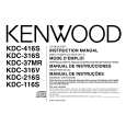
KDC-216S/2018
MICROCOMPUTER'S TERMINAL DESCRIPTION
qTerminal Description
Pin 1 2 3 4 5 6 7 8 9 10 11 12 13 14 15 16 17 18 19 20 21 22 23 24 25 26 27 28 29 30 31 32 33 34 35 36 37 38 39 40 41 42 43 44 45 46 Function AV CONT IC2 TYPE0 IC2 TYPE1 AVSS M MUTEL N.C AVREF1 ILLUMI L RES PANEL L DATAL L DATAS L CLK N.C N.C CH-DATAC CH-DATAH CH-CLK L CE N.C M RST M STOP MOSW PLL SCL AM+B FM+B M-SCL DSI LO/EJ SW3 R DATA R QUAL VSS1 SD IC2 SCL M-SDA PLL SDA IC2 SDA MUTE N.C AFC CH-REQH CH-CON N.C P MUTE SVR I/O O I I I O I O O I I O O O O I O I/O O O O O O O O O I/O O I/O I I I I O I/O I/O I/O O O O O O O O O Description A/D converter reference voltage control output IC2 setting terminal IC2 setting terminal Ground connection terminal Muting request from the MICOM. of CD mecha. Not used D/A converter reference voltage input Illumination AVR ON/OFF control output Reset output to the LCD driver IC Panel open/close detection input Data input from the LCD driver IC Data output to the LCD driver IC Clock output to the LCD driver IC Not used Not used Data input from changers Data output to changers Clock input/output with changers CE output to the LCD driver IC Not used Reset output to the MICOM. of CD mecha. Stop request to the MICOM. of CD mecha. CD mechanism loading motor control output Clock output to the tuner pack AM+B control FM+B control Clock input/output with the MICOM. of CD mecha. DSI output CD mecha.Loading/Eject switching output Down & limit switch detection input Data input from RDS decoder Quality input from RDS decoder Ground connection terminal SD input from the tuner pack Clock output to the E-VOL. IC Data input/output with the MICOM. of CD mecha. Data input/output with the tuner pack Data input/output with the E-VOL. IC Mute control output Not used AFC control output Request output to changers Changer control Not used Power IC mute control Power lC reset terminal Processing Operation �Hi�: ON / �Lo�: OFF �Lo�: Initial value �Lo�: Initial value connected to GND �Lo�: Mute request
�Hi�: AVR ON �Lo�: Reset �Lo�: Panel closed
�Hi�: Active �Lo�: Reset �Lo�: Stop �Hi�: Loading & Eject / �Lo�: other �Hi�: during AM reception �Hi�: during FM reception �Hi�: LED ON �Lo�: Loading / �Hi�: Eject �Hi�: Chucking / �Lo�: Pickup most inner position
connected to GND �Hi�: Station detected
�Hi�: Mute ON / �Lo�: Mute OFF �Lo�: during FM seek �Lo�: Request �Lo�: Standby / �Hi�: ON �Lo�: Mute When the momentary power down, after ACC OFF/ON is detected and after POWER ON/ OFF, the output goes �Hi� temporarily. �Hi�: POWER ON mode �Hi�: POWER ON mode except ALL OFF mode �Hi�: during FM/AM reception �Hi�: ACC OFF / �Lo�: ACC ON �Hi�: When momentary power down detected or BU OFF / �Lo�: BU ON
47 48 49 50 51 52 53 4
STBY P CON P ANT BEEP ACC DET BU DET N.C
O O O O I I O
Power IC standby control output Power control Antenna control BEEP sound output ACC detection input Momentary power down detection input Not used
|
|
|
> |
|