|
|
|
Categories
|
|
Information
|
|
Featured Product
|
|
|
 |
|
|
There are currently no product reviews.
 ;
Thanks to this service manual I repaired my old camcorder! The manual perfectly explains how to disassemble the camcorder step by step.
;
This manual is very useful because it presents the technical specifications of the cd player, including the manufacturer of the reader, this helps if you need to replace it. It also displays the settings and layout of the circuit.
;
Manual was a good representation of service infomation for the EWV404. It worked well for my repair.
 ;
Great quality copy, right what I was looking for, all I need to fix my radio.
Thanks
;
I BOUGHT A PAIR OF INFINITY VINTAGE SPEAKERS THAT REQUIRED TO BE REPAIRED AND THE ELECTRONIC TECHNICIAN ASKED ME FOR THE SERVICE MANUAL.
I TRIED TO GET IT AT THE MANUFACTURER'S SITE WITH NO SUCCESS, SO I STARTED TO LOOK FOR IT IN THE WEB FOR A LONG TIME, UNTIL I FOUND THE SERVICE MANUAL IN THIS EXCELLENT SITE "OWNER'S MANUAL.COM".
NOW I HAVE MY SPEAKERS WORKING AND ENJOYING THE MUSIC I LIKE.
THANKS TO "OWNER`S MANUAL.COM" I RECOMMEND THIS SITE TO EVERYONE.
KDC-2023, 2024A/SG/SYA/SYG, 2094YA/YG, 222/S,3023
ADJUSTMENT
1. IC10 (TDA7513) -The Tuner adjustment method
� When IC10 and its circumference are fixed, according to the following order, it readjusts if needed. � The adjustment item changes with parts to exchange. Please refer to "Parts vs Adjustment item table". 1-1. VCO Coil Adjustment -- Adjustment of Tunning Voltage Voltage Check Point : Vt-Check Land (PWB Side_B, around D506) Adjustment Coil : L507 (VCO Coil) The adjustment method : VCO coil is turned and adjusted according to the following tables.
TYPE E/M K J W(Wide Band) Mode AM AM FM FM freq. 1611kHz 1700kHz 90.0MHz 108.0MHz Voltage 5.5 ± 0.1(V) 5.8 ± 0.1(V) 5.6 ± 0.1(V) 7.2 ± 0.1(V) Fig (C) (C) (C) (C)
1-3. Adjustment of FM_ANT&RF Coil Voltage Check Point : S_METER-Check Land (PWB Side_B, around W572) Adjustment Coil : ANT_Coil = L505 RF_Coil = L506 Setting of Signal Generator : Refer to the following tables.
TYPE E/M K J W(Wide Band) MODE FM FM FM FM freq. 87.5MHz 87.9MHz 76.0MHz 65.0MHz Mod. OFF OFF OFF OFF ANT Input 5 or 11dBuEMF 5 or 11dBuEMF 5 or 11dBuEMF 5 or 11dBuEMF Fig (A),(C) (A),(C) (A),(C) (A),(C)
xThe appearance and the coil with which S-METER DC voltage serves as the maximum are turned and adjusted in the above-mentioned SG input. �By the above-mentioned adjustment method, same adjustment is performed to both sides (ANT&RF Coil). 1-4. Adjustment of STEREO (adjustment of 456k-VCO) Adjust in TEST_MODE � How to enter the test mode While pressing on [ FM ] and [ PRESET 6 ] keys, reset the unit. � Adjustment method Complete on condition that show "ALL OFF" when pressing on [ PRESET 1 ] and [ PRESET 6 ] keys. (Writing adjustment valve to the EEPROM.) Effect of adjustment is in cofirmation of adjustment status at [ PRESET 4 ] key. � Display of [ PRESET 4 ] Adjustment "OK" : 14seg model "E2P OK" 7seg model "EPO" Adjustment "NG" : 14seg model "E2P ERR" 7seg model "EPE" � Releasing the test mode Reset mode only. ACC off, Power off, Power down and Remove the panel mode is not releasing.
M : AM Adjustment For Your Information : The frequency of SET is only set up by Pre-Set-Key in case this adjustment 1-2. Adjustment of 1st & 2nd-MIX Coil Voltage Check Point : S_METER-Check Land (PWB Side_B, around W572) Adjustment Coil : 1stIFT = L508 / 2ndIFT = L509 Setting of Signal Generator : Refer to the following tables
TYPE K E,M,J,W MODE AM AM freq. 1000kHz 999kHz Mod. OFF OFF ANT Input 35dBuEMF 35dBuEMF Fig (B),(C) (B),(C)
xThe appearance and the coil with which S-METER DC voltage serves as the maximum are turned and adjusted in the above-mentioned SG input. �By the above-mentioned adjustment method, same adjustment is performed to both sides (1st&2nd MIX Coil).
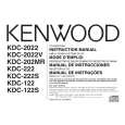
(REAR VIEW)
(TUNER ANT)
[Fig.1]
FM-SG AM-SG
(A) (B)
L505 L506 L507 L508
(C) DC Voltmeter Vt Check Land IC10
L509
S-METER Check Land (OVER VIEW) (UNDER VIEW)
[Fig.2]
[Fig.3]
8
|
|
|
> |
|