|
|
|
Categories
|
|
Information
|
|
Featured Product
|
|
|
 |
|
|
There are currently no product reviews.
 ;
Thought I would never find a copy of the Technics SX-EN2 Service Manual until I found Owner-Manuals.com. Price was very fair and I received the download promptly. While a photocopy, it is quite readable and includes all the pertinent information and diagrams. Thank you Owner-Manuals!
 ;
I really like this manual and it's reliable.I found and bought easly.thank you.
;
Thank you very much. the Instruction corresponds to my expectations. Sent it in time. I don't regret that paid money.
;
Good quality. Quick service. I recommend to everyone.
;
Very good quality scan of the document. I am very pleased with what I got.
KDC-2023, 2024A/SG/SYA/SYG, 2094YA/YG, 222/S,3023
ADJUSTMENT
1. IC10 (TDA7513) -The Tuner adjustment method
� When IC10 and its circumference are fixed, according to the following order, it readjusts if needed. � The adjustment item changes with parts to exchange. Please refer to "Parts vs Adjustment item table". 1-1. VCO Coil Adjustment -- Adjustment of Tunning Voltage Voltage Check Point : Vt-Check Land (PWB Side_B, around D506) Adjustment Coil : L507 (VCO Coil) The adjustment method : VCO coil is turned and adjusted according to the following tables.
TYPE E/M K J W(Wide Band) Mode AM AM FM FM freq. 1611kHz 1700kHz 90.0MHz 108.0MHz Voltage 5.5 ± 0.1(V) 5.8 ± 0.1(V) 5.6 ± 0.1(V) 7.2 ± 0.1(V) Fig (C) (C) (C) (C)
1-3. Adjustment of FM_ANT&RF Coil Voltage Check Point : S_METER-Check Land (PWB Side_B, around W572) Adjustment Coil : ANT_Coil = L505 RF_Coil = L506 Setting of Signal Generator : Refer to the following tables.
TYPE E/M K J W(Wide Band) MODE FM FM FM FM freq. 87.5MHz 87.9MHz 76.0MHz 65.0MHz Mod. OFF OFF OFF OFF ANT Input 5 or 11dBuEMF 5 or 11dBuEMF 5 or 11dBuEMF 5 or 11dBuEMF Fig (A),(C) (A),(C) (A),(C) (A),(C)
xThe appearance and the coil with which S-METER DC voltage serves as the maximum are turned and adjusted in the above-mentioned SG input. �By the above-mentioned adjustment method, same adjustment is performed to both sides (ANT&RF Coil). 1-4. Adjustment of STEREO (adjustment of 456k-VCO) Adjust in TEST_MODE � How to enter the test mode While pressing on [ FM ] and [ PRESET 6 ] keys, reset the unit. � Adjustment method Complete on condition that show "ALL OFF" when pressing on [ PRESET 1 ] and [ PRESET 6 ] keys. (Writing adjustment valve to the EEPROM.) Effect of adjustment is in cofirmation of adjustment status at [ PRESET 4 ] key. � Display of [ PRESET 4 ] Adjustment "OK" : 14seg model "E2P OK" 7seg model "EPO" Adjustment "NG" : 14seg model "E2P ERR" 7seg model "EPE" � Releasing the test mode Reset mode only. ACC off, Power off, Power down and Remove the panel mode is not releasing.
M : AM Adjustment For Your Information : The frequency of SET is only set up by Pre-Set-Key in case this adjustment 1-2. Adjustment of 1st & 2nd-MIX Coil Voltage Check Point : S_METER-Check Land (PWB Side_B, around W572) Adjustment Coil : 1stIFT = L508 / 2ndIFT = L509 Setting of Signal Generator : Refer to the following tables
TYPE K E,M,J,W MODE AM AM freq. 1000kHz 999kHz Mod. OFF OFF ANT Input 35dBuEMF 35dBuEMF Fig (B),(C) (B),(C)
xThe appearance and the coil with which S-METER DC voltage serves as the maximum are turned and adjusted in the above-mentioned SG input. �By the above-mentioned adjustment method, same adjustment is performed to both sides (1st&2nd MIX Coil).
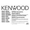
(REAR VIEW)
(TUNER ANT)
[Fig.1]
FM-SG AM-SG
(A) (B)
L505 L506 L507 L508
(C) DC Voltmeter Vt Check Land IC10
L509
S-METER Check Land (OVER VIEW) (UNDER VIEW)
[Fig.2]
[Fig.3]
8
|
|
|
> |
|