|
|
|
Categories
|
|
Information
|
|
Featured Product
|
|
|
 |
|
|
There are currently no product reviews.
 ;
Excellent high quality schematics brought my old Heidelberg back to life. Fast download at a reasonable price. Thanks.
;
This document is just what I was looking for, it´s very useful, it contains adjustment procedures for the final stage of the power amp and also
has a complete wiring diagram and description of the main semiconductors used in the design.
;
Dear Sirs,
Thank you for the fast support, the manual does provide all necessary information to repair the radio. All schematics are in a good quality for reading.
The manual fits 100% to my requirements as a technican.
Kind regards Thomas
;
the big video recorder format s-vhs many features delicate in loading system of the cassette. Such machines are no longer manufactured, it would be too expensive.
 ;
THIS MANUAL IS VERY GOOD AND VERY CLEAR
PLEASE NOTE IT DOES NOT CONTAIN THE SETUP INFORMATION TO ALIGHN THE GEARS IN THE CD MECH IT DOES SHOW ALL THE PARTS AND THEIR LOCATIONS .
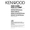
KDC-CX89/CMP59FM/C719MP/CPS89MP
ADJUSTMENT
L.P.S initial position adjustment procedure
1. Connect the changer to the H/U. 2. While holding the magazine eject button of the changer, press the reset button of the H/U. 3. After about 3 seconds, release the magazine eject button. 4. Press the SRC button of the H/U to enter the CD-CH mode, and the H/U's display section indicates "E-88". 5. Move the mechanism deck to around the 1st stage by pressing the DISC- or DISC+ button. 6. Insert the adjustment tool (W02-0635-00) into the tool hole on the changer mechanism. 7. Then press the DISC+ button to move the mechanism deck until the mechanism's slider hits the adjustment tool. 8. When the motor locks (stops), press the REPEAT key of the H/U. When the REPEAT key is pressed, the mechanism moves automatically to the 1st stage and the initial position adjustment completes. (The data is written in the EEPROM at this time.)
W05-0635-00
For KDC-CMP59FM
RF MODULATOR UNIT
1. DC balance adjustment (VR301) While observing the waveform with an oscilloscope at pin 13 of IC301, adjust VR301 to minimize the waveform level. 2. PLL control voltage adjustment (VC301) First set the transmission frequency to �87.9MHz with the commander, then adjust VC301 so that the DC Voltage at the +pole of C317, measured using a multi-meter or digital tester, is +3V (±0.1V). �NOTE: E type is 87.7MHz. 3. Modulation level adjustment (VR303) The method uses a standard receiver or tuner. Adjust VR303 so that the output level from the standard receiver or tuner is as specified.
9
|
|
|
> |
|