|
There are currently no product reviews.
 ;
The manual is very good quality. very good graphics. complete
;
Excellent printing quality.
A complete and very usefull service manual with all details.
GREAT SERVICE AT VERY LOW PRICE!
A+++++++++++++++++++++++++
;
Excellent, very professional, fast, reliable, congratulations thank you.
;
Excellent printing quality.
A complete and very usefull service manual with all details.
GREAT SERVICE AT VERY LOW PRICE!
A+++++++++++++++++++++++++
;
Excellent printing quality.
A complete and very usefull service manual with all details.
GREAT SERVICE AT VERY LOW PRICE!
A+++++++++++++++++++++++++
KDC-MP425/MP6026 KDC-W6027/W6027Y
DISASSEMBLY FOR REPAIR
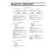
How to Disassemble (PANEL ASSY)
1) Remove four screws (A). 2) While holding the section (B) indicated with arrows, pull and remove PANEL ASSY.
How to install knob (SRC)
1) Place knob (F) and knob (G) in the positions indicated in the diagram below. 2) While keeping these positions, use a piece of adhesive tape (H) to hold knobs in position, as shown in the diagarma.
A x2
3) Set the rotary (J) position as shown in the diagram. 4) While keeping the letters �SRC� horizontally in position, set it to the rotary on the panel. 5) Remove the adhesive tape (H).
A x2
F G
H
B B
B
B
J
3) Pull SWITCH UNIT (C) as indicated in the diagram and remove knob (D). (The knob (D) is attached to the rotary with hook (E) and it is not possible to remove hook (D) only.)
D E
C
3
|