|
There are currently no product reviews.
 ;
Great tape deck manual!
I'm very positively surprised, because it is a very long manual, lot of pages, drawings, diagrams, description of how to make the alignment and adjustment procedures.
It is as good as the old "Naka" manuals from the 1970's - if somebody have seen them, they know what I mean by that.
I recommend to buy this very much !
;
I am a vintage hifi collector. No way to fix that device without the appropriate service manual...thanks to your site I got it and every thing is easier now. I got the manual right after ordering: fast cheap accurate ... thank you
;
Wonderful job clear. Qick fantastic. These people are really good. If even a problem arise they are wonderful assisting you. These scheme is so net despite this is a very old TV. Thank you for everything!!!!!!!!
;
Detailed schematic diagram, manual for professionals
;
Good service manual,exploded view,adjusment and test point locations,head alignment,mechanical checks and adjusments,all perfect.
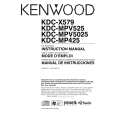
KDC-MPV5025/MPV525 KDC-MPV7026/WV6027
DISASSEMBLY FOR REPAIR
How to Disassemble (PANEL ASSY)
1) Remove four screws (A). 2) While holding the section (B) indicated with arrows, pull and remove PANEL ASSY.
How to install knob (SRC)
1) Place knob (F) and knob (G) in the positions indicated in the diagram below. 2) While keeping these positions, use a piece of adhesive tape (H) to hold knobs in position, as shown in the diagarma.
A x2
3) Set the rotary (J) position as shown in the diagram. 4) While keeping the letters �SRC� horizontally in position, set it to the rotary on the panel. 5) Remove the adhesive tape (H).
A x2
F G
H
B B
B
B
J
3) Pull SWITCH UNIT (C) as indicated in the diagram and remove knob (D). (The knob (D) is attached to the rotary with hook (E) and it is not possible to remove hook (D) only.)
D E
C
3
|