|
There are currently no product reviews.
 ;
Hi - happy with what I received but not quite what I wanted - my fault I assumed that service manual would also include operational instructions which is what I needed - all I needed to know was how to turn the radio - thanks
;
this Manual very important when i buy this Manual i already fix the trouble of my Camera..... thanks keep up the good work.!
 ;
This service manual helped me to repair my PIONEER. Iam very satisfied, that I found it here.
Even the price of manual was not so high that person would not be able to spend a few money.
But that is very worth spent money. Thanks
;
Excellent quality service manual. Quick processing, fair prices. Love to do business again. Thank you!!!
;
Excellent service manual, the only known point of note is the alignment of improvability scanned pages within the pdf page. The resolution is good.
3.1.4 Removing the side panel (See Fig.4) � Prior to performing the following procedure, remove the front panel assembly as required. (1) Remove the screw B and two screws C attaching the heat sink on the left side of the main body, and remove the side panel.
C
B
C
Side panel
Fig.4 3.1.5 Removing the rear bracket (See Fig.5) � Prior to performing the following procedure, remove the bottom cover. (1) Remove the three screws D, three screws E and two screws F attaching the rear bracket on the back side of the main body. (2) Remove the rear bracket.
E
F
Rear bracket
E
F
D
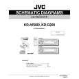
Fig.5 3.1.6 Removing the main board (See Fig.6) � Prior to performing the following procedure, remove the front panel assembly, front chassis assembly, side panel, bottom cover and rear bracket. (1) Remove the two screws G attaching the main board. (2) Disconnect the connector CN501 and remove the main board.
D
Main board CN501
G
G
Fig.6
(No.MA030)1-7
 $4.99 KD-G200 JVC
Parts Catalog Parts Catalog only. It's available in PDF format. Useful, if Your equipment is broken and You need t…
|