|
There are currently no product reviews.
 ;
Das Service Manual war von der ersten bis zur letzten Seite sehr informativ und hilfreich. Die Darstellung aller Teile war klar und der Text gut lesbar.
Vielen Dank, das war nicht der letzte Download bei ownner-manuals.com.
;
It's a grate service manuals.Have many details and the writing it's so clear.You have all you want in manual,nothing missing,belive me.I'm verry satisfied of this manual.
;
Great scanned service manual
Usefull informations.
I will buy again!
Best Regards
;
The manual describes this product very good. It has the basic things to know and also a more detailed look. Very well made!
;
An excellent document to assist in the repair of my old personal tape player. It includes full circuit diagrams and physical layout drawings and full instructions on disassembly and fault finding.
Well worth the meagre price.
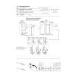
3.1.7 Removing the rear bracket (See Fig.12) � Prior to performing the following procedures, remove the front panel assembly, heat sink, top chassis assembly and main board. (1) From the rear side of the main board, remove the wires from the rear bracket in the direction of the arrow. (2) Remove the screw K, screw L, three screws M and screw N attaching the rear bracket to the main board. Reference: After attaching the rear bracket to the main board, pass the wires through the wire holder and insert them into the slots of the rear bracket.
Wires
Main board Wire holder
Rear bracket
Slots Rear bracket
K
L
MN
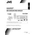
Fig.12 3.1.8 Removing the front door mechanism assembly (See Fig.13) � Prior to performing the following procedures, remove the front panel assembly, heat sink, top chassis assembly and main board. (1) From the top side of the bottom chassis assembly, remove the screw P attaching the FPC guide to the bottom chassis. (2) Remove the five screws Q attaching the front door mechanism assembly to the bottom chassis. Reference: When attaching the screws P and Q, apply a locking agent them. (3) Take out the front door mechanism assembly from the bottom chassis.
M
Front door mechanism assembly Bottom chassis
Q
Q
FPC guide
Fig.13
P
(No.MA152)1-11
 $4.99 KDLHX552 JVC
Owner's Manual Complete owner's manual in digital format. The manual will be available for download as PDF file aft…
|