|
|
|
Categories
|
|
Information
|
|
Featured Product
|
|
|
 |
|
|
There are currently no product reviews.
 ;
complete wiring diagram, without the part list. high quality copy. thanks for promptly.
;
Well done scan of a useful manual. It will be useful in my workbench!!
 ;
Excelent scan job. It's a fully detailed service manual of this model.
;
Do a quick order, scan quality is high.
I recommend to all!
;
This manual is perfect! Just what I needed. Thanks!
KD-LX10/KD-LX30
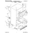
Removing the CD mechanism control board (See Fig.1 and 2)
1. Remove the screw N and the pickup cover attached to the front bracket with the two double-sided tapes. 2. Unsolder the part f and g on the CD mechanism control board. 3. Remove the stator fixing the CD mechanism control board and the damper bracket (To remove the stator smoothly, pick up the center part). 4. Remove the screw F attaching the CD mechanism control board. 5. Remove the CD mechanism control board in the direction of the arrow while releasing it from the two damper bracket slots i and the front bracket slot j. 6. Disconnect the flexible wire from connector on the pickup unit. ATTENTION: Turn the FD gear in the direction of the arrow to move the entire pickup unit to the appropriate position where the flexible wire of the CD mechanism unit can be disconnected easily (Refer to Fig.2).
FD gear Damper bracket
Pickup cover
IN
I
f
F
I
i CD mechanism control board
Double-sided tape
Front bracket
j
Fig.1
Pickup unit Flexible wire Shift the lock
Fig.2
Removing the loading motor (See Fig.3 to 5)
Prior to performing the following procedure, remove the CD mechanism control board and the pickup cover. 1. Remove the two springs k attaching the CD mechanism ass�y and the front bracket. 2. Remove the two screws G and the front bracket while pulling the flame outward. 3. Remove the belt and the screw H from the loading motor.
CD mechanism control board
k
k
G G
Loading motor Front bracket
Fig.3
Pull outward
Front bracket
Pull outward
Flame
Fig.4
2-7
|
|
|
> |
|