|
There are currently no product reviews.
 ;
The quality of this manual is good. It has all schematics and setup information for both the MDS-B3 and the MDS-B4. The scan quality is quite good, all pages are readable, This service manual also contains scans of the operating instructions from the User manual.
 ;
Quick site processing. A complete and very useful manual with all details. Thank you!
;
Das Service Manual war von der ersten bis zur letzten Seite sehr informativ und hilfreich. Die Darstellung aller Teile war klar und der Text gut lesbar.
Vielen Dank, das war nicht der letzte Download bei ownner-manuals.com.
;
It's a grate service manuals.Have many details and the writing it's so clear.You have all you want in manual,nothing missing,belive me.I'm verry satisfied of this manual.
;
Great scanned service manual
Usefull informations.
I will buy again!
Best Regards
KD-LX333R
Disassembly method
<Main body>
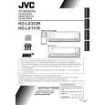
Removing the top chassis (See Fig.1 to 5)
1. Remove the two screws A attaching the bottom cover to the top chassis on the bottom of the body. 2. Remove the two screws B attaching the top chassis on both sides of the body. 3. Remove the two screws C and the two screw D attaching the heat sink on the left side of the body. 4. Remove the two screws E and the screw F on the back of the body. 5. Remove the two screws G on the upper side of the body. 6. Move the top chassis upward and disconnect the CD mechanism connector from the main board connector by pulling it. Remove the top chassis from the body. Fig.2
Bottom cover
A A
Fig.1
Top chassis
B
C
Top chassis
Heat sink
D
Fig.3
B
E
F
Top chassis
Fig.4
G G
Fig.5
1-4
|