|
|
|
Categories
|
|
Information
|
|
Featured Product
|
|
|
 |
|
|
There are currently no product reviews.
 ;
Complete MFG Service Manual at a good price FAST !
;
Downloaded the manual, reasonably straightforward, pretty much exactly as advertised.
 ;
very helpfull
circuit diagram and sparepart list available
;
Very good reproduction (copy) of original manual. Didn't have a parts list, but schematic was completely labeled with parts. Complete instructions on how to adjust mechanical functions of the 8-track deck. Well worth having and at a very reasonable cost.
;
It's a full manual. All the parts are in there. I haven't found the problem yett, but I am working on it; hope I can rebuild the part myself. To make it more secure and unbreakable this time. Because the part has failed several times before and costs a lot to let it be repaired.
Thanks so much for this rich illustrated and parted manual.
3.1.4 Removing the side panel (See Fig.4) Reference: Remove the front panel assembly as required. (1) Remove the screw B and two screws C attaching the side panel on the left side of the main body. (2) Remove the side panel from the main body.
C
B
C
Side panel
Fig.4 3.1.5 Removing the rear bracket (See Fig.5) � Remove the bottom cover. (1) Remove the three screws D, three screws E and two screws F attaching the rear bracket on the back side of the main body. (2) Remove the rear bracket. 3.1.6 Removing the main board (See Figs.5 and 6) � Remove the front panel assembly, bottom cover and side panel. Reference: Remove the front chassis assembly as required. (1) Remove the three screws D attaching the rear bracket on the back side of the main body. (See Fig.5.) (2) Remove the two screws G attaching the main board. (See Fig.6.) (3) Disconnect the connector CN501 on the main board from the main body and take out the main board with the rear bracket. (See Fig.6.) Reference: Remove the rear bracket from the main body as required. (See "3.1.5 Removing the rear bracket".)
Rear bracket
E
F
E
F
D
Fig.5
D
Main board
CN501
G
G
Rear bracket
Fig.6
1-8 (No.MA121)
 $4.99 KD-S11 JVC
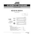
Circuit Diagrams Set of circuit diagrams. The diagrams will be provided as PDF file. The file will be delivered after… 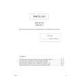 $4.99 KD-S11 JVC
Parts Catalog Parts Catalog only. It's available in PDF format. Useful, if Your equipment is broken and You need t…
|
|
|
> |
|