|
|
|
Categories
|
|
Information
|
|
Featured Product
|
|
|
 |
|
|
There are currently no product reviews.
 ;
Received via e-mail this PDF manual is worth the money. This is a quality scan of a manual in excellent condition and is just as good as having the original manual in hand. I have later seen the original manual and it was printed in colour, but this particular manual is black & white but scan resolution is high end quality! All drawings and pictures are presented in great detail. So, nearly perfect score in my opinion.
If you own the turntable you also should own the manual!
 ;
I was very satisfied with the service manual I ordered and downloaded. I will definitely buy again from this seller.
 ;
Great product. Recieved it fast...exactly as advertised.
 ;
Manuals were delivered promptly and were correct as advertised. No issues with the download link which was provided promptly after everything was processed. Very pleasant experience
 ;
Paid for service manual & got the download fast - worth a visit if you need a service manual
KD-S6250/KD-S580
Removing the feed motor ass�y (See Fig.10)
Prior to performing the following procedure, remove the CD mechanism control board, the front bracket (loading motor) and the CD mechanism ass�y. 1. Remove the two screws K and the feed motor ass�y.
FD screw Part n Feed motor ass�y Part O
K
Pickup unit
FD gear
Pickup unit
Fig.10
Removing the pickup unit (See Fig.10 and 11)
*Prior to performing the following procedure, remove the CD mechanism control board, the front bracket (loading motor), the CD mechanism ass�y and the feed motor ass�y. 1. Detach the FD gear part of the pickup unit upward. Then remove the pickup unit while pulling out the part n of the FD screw. ATTENTION: When reattaching the pickuap unit, reattach the part o of the pickup unit, then the part n of the FD screw. 2. Remove the screw L attaching the nut push spring plate and the pickup mount nut from the pickup unit. Pull out the FD screw. Fig.11
FD screw
L
Nut push spring plate Pickup mount nut
Pickup unit
Removing the spindle motor (See Fig.12 and 13)
Prior to performing the following procedure, remove the CD mechanism control board, the front bracket (loading motor), the CD mechanism ass�y and the feed motor ass�y. 1. Turn up the CD mechanism ass�y and remove the two springs p on both sides of the clamper arms. Open the clamper arm upward. 2. Turn the turn table, and remove the two screws M and the spindle motor.
p
p
Fig.12
Spindle motor
M
M
Fig.13
1-10
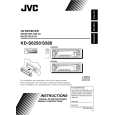
 $4.99 KD-S6250 JVC
Owner's Manual Complete owner's manual in digital format. The manual will be available for download as PDF file aft…  $4.99 KD-S6250 JVC
Parts Catalog Parts Catalog only. It's available in PDF format. Useful, if Your equipment is broken and You need t…
|
|
 |
> |
|
