|
|
|
Categories
|
|
Information
|
|
Featured Product
|
|
|
 |
|
|
There are currently no product reviews.
 ;
One address for rare manuals.Very good copy. Thank you.
Your
Klaus Husse
;
All ok. I pay 5 $ and now i have 92 pages of good scaned service manual for my oooooold akai. Now i will try to repair it.
;
good and ok, very nice , good and ok, very nice, good and ok, very nice
;
Super manual it contains all the things you need to service your Marantz 2100.
;
A very easy to understand and use manual. Well worth the money.
KD-S7R
<CD mechanism section>
Prior to disassembling the CD mechanism, remove the following parts. The front panel unit and the front chassis (Refer to Fig.1 and 2)
CD mechanism Damper bracket assembly I I
m
f m h
I
The heat sink (Refer to Fig.3) The bottom cover (Refer to Fig.4) The main amplifier board (Refer to Fig.5 and 6) The CD mechanism assembly (Refer to Fig.7) Front bracket
i
F
g
j CD mechanism
control board Fig.10
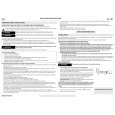
Removing the CD mechanism control board(See Fig.10 and 11)
1. Unsolder the part f and g on the CD mechanism control board. 2. Remove the stator fixing the CD mechanism control board and the damper bracket (To remove the stator smoothly, pick up the center part). Remove the screw F attaching the CD mechanism control board. Remove the CD mechanism control board in the direction of the arrow while releasing it from the two damper bracket slots i and the front bracket slot j. Disconnect the flexible wire from connector on the pickup unit. ATTENTION: Turn the FD gear in the direction of the arrow to move the entire pickup unit to the appropriate position where the flexible wire of the CD mechanism unit can be disconnected easily (Refer to Fig.11).
Pickup unit Flexible wire Shift the lock
FD gear
Fig.11
CD mechanism control board
k k
G G
Loading motor Front bracket Fig.12
Pull outward
Pull Front bracket outward
Flame
Fig.13
1-8
|
|
|
> |
|