|
|
|
Categories
|
|
Information
|
|
Featured Product
|
|
|
 |
|
|
There are currently no product reviews.
 ;
Print was clear and easy to read. Thank you Joe joeoldaudio
;
Very great deal. In a few minutes a have the manual, that I needed. Thanl you very much
;
Manual was complete. Received it quickly. No problems
;
Product was very good. Received quickly and complete
 ;
The Sony AV-3600 service manual was what I needed for the repair of this unit
Thanks for the good service
Dave
3.2
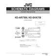
CD mechanism assembly section
� Remove the CD mechanism assembly from the main body. (See "3.1.5 Removing the CD mechanism assembly".) 3.2.1 Removing the mechanism control board (See Fig.1) (1) From the bottom side of the CD mechanism assembly, solder the short sections on the flexible wire. Caution: Solder the short sections on the flexible wire before disconnecting the flexible wire from the connector CN601 on the mechanism control board. If you do not follow this instruction, the CD pickup may be damaged. (2) Disconnect the flexible wire from the connector CN601 on the mechanism control board. (3) Disconnect the flexible wire from the connector CN602 on the mechanism control board. (4) Remove the solders from the soldered sections a on the mechanism control board and remove the wires of the feed motor. (5) Remove the solders from the soldered sections b on the mechanism control board, and remove each wire of the spindle motor and other parts. (6) Remove the five screws A attaching the mechanism control board. Caution: When reassembling, remove the solders from the short sections after connecting the flexible wire to the connector CN601 on the mechanism control board.
Short sections Flexible wire
CD mechanism assembly
A
Feed motor
a
CN601
A
A
A
Spindle motor
b
A
CN602
Mechanism control board Fig.1
(No.MA162)1-11
 $4.99 KD-SHX750 JVC
Parts Catalog Parts Catalog only. It's available in PDF format. Useful, if Your equipment is broken and You need t…
|
|
|
> |
|