|
There are currently no product reviews.
 ;
+++ Is is fine, that was what i looking for. Thanks! +++
;
A very good complete archive, i am very satisfied for document.
 ;
The Service Manual received was helpful. The electronic information is exactly what I needed.
;
The Manual was perfect.
The deliverie was perfect.
Thanks
;
Found website easy to use and manual very clear. First class service
KD-SX991R / KD-SX911R
Removing the feed motor assembly (See Fig.10)
Prior to performing the following procedure, remove the CD mechanism control board, the front bracket (loading motor) and the CD mechanism assembly. 1. Remove the two screws F assembly. and the feed motor
Pickup unit FD screw Feed motor assembly Part i
Part j
F
FD gear
Pickup unit
Removing the pickup unit (See Fig.10 and 11)
Prior to performing the following procedure, remove the CD mechanism control board, the front bracket (loading motor), the CD mechanism assembly and the feed motor assembly.
Nut push spring plate
Fig.10
G
Pickup mount nut
1. Detach the FD gear part of the pickup unit upward. Then remove the pickup unit while pulling out the part i of the FD screw. ATTENTION: When reattaching the pickup unit, reattach the part j of the pickup unit, then the part i of the FD screw. 2. Remove the screw G attaching the nut push spring plate and the pickup mount nut from the pickup unit. Pull out the FD screw.
FD screw
Pickup unit
Fig.11
k
k
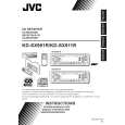
Removing the spindle motor (See Fig.12 and 13)
Prior to performing the following procedure, remove the CD mechanism control board, the front bracket (loading motor), the CD mechanism assembly and the feed motor assembly. 1. Turn up the CD mechanism assembly and remove the two springs k on both sides of the clamper arms. Open the clamper arm upward. 2. Turn the turn table, and remove the two screws H and the spindle motor. Fig.12
Spindle motor
H
H
Fig.13
1-11
 $4.99 KDSX911R JVC
Owner's Manual Complete owner's manual in digital format. The manual will be available for download as PDF file aft…
|