|
|
|
Categories
|
|
Information
|
|
Featured Product
|
|
|
 |
|
|
There are currently no product reviews.
 ;
Very complete shop manual. It contains everything needed to troubleshoot bascially any problem. Instructions, diagrams, schmeatics, illustrations... it's all there. Highly recommended!
;
Great product, very good quality, found all needed information. Thanks
;
Excellent quality, helped to fix problem. Thank you very much!!!!
;
I thank Owner-Manuals.com for providing the necessary manual very quickly, and it was very helpful in repairing my personal Audio System and I once again thank them for the wonderful customer's service satisfaction.
Thanks.
;
Everything fine: quick service, no glitch and above all a very good quality of the Pdf file. Thank you!
D
C
E
B
A
F
40
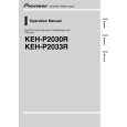
6. Multi-CD player 8. Note: (sold separately) Depending on kind of vehicle, the function 18. Connecting cords with RCA pin plugs sure connect 2* 5* and 4* to 3*. (sold separately) 1. This Product 4. IP-BUS cable 2. Rear output 5* 4* 20. Blue/white 12 V DC). 21. System remote control When not using this terminal, To Auto-antenna relay control terminal (max. 300 mA 12 V DC). 10. Cap (1*) 5. IP-BUS input (Blue) 7. Fuse 3. Antenna jack (sold separately)
1
type of vehicle, never connect 6* and 7*. 25. Left 26. Right ON/OFF. 27. Rear Speaker 28. Perform these connections when using 17. Speaker leads White : Front left + White/black : Front left â� the optional amplifier. Gray : Front right + Gray/black : Front right â� + â� + â�
1
of 3* and 5* may different. In this case, be
1*
3* 2* 19. Power amp
9. Connect leads of the same To system control terminal of
color to each other . the power amp (max. 300 mA
2
2
do not remove the cap. 22. Blue/white (7*)
11. (3*) 12. Yellow (2*) 23. Blue/white (6*)
KEH-P2033R/XM/EW
Back-up To terminal always supplied 24. The pin position of the ISO connector will differ (or accessory) with power regardless of depends on the type of vehicle. Connect 6* and 7*
ignition switch position. when Pin 5 is an antenna control type. In another
13. (5*) 14. Red (4*)
Accessory To electric terminal controlled (or back-up) by ignition switch (12 V DC)
3
3
15. Black (ground)
To vehicle (metal) body.
4
4
16. ISO connector Green : Rear left
Note: Green/black : Rear left In some vehicles, the ISO connector may be Violet : Rear right divided into two. In this case, be sure to Violet/black : Rear right connect to both connectors.
|
|
|
> |
|