|
|
|
Categories
|
|
Information
|
|
Featured Product
|
|
|
 |
|
|
There are currently no product reviews.
 ;
This is a good quality scan of the Operation & Maintenance (Service) Manual for the PAL version of this high-band broadcast umatic, BVU-800P
All schematics and lineup procedures appear to be included in this one manual AFAICT.
The file size is just over 113 MB which gives an idea of the quality and number of pages.
All of the schematics, which contain some fairly small print, are easily readable when you zoom into the page.
John Thompson, Newcastle Upon Tyne, England.
;
Good quality, all schematics of few of models. There is also short form of user manual and regulation manual.
;
Perfect copy of the service manual. you can enlarge every page, and it comes up
with all details.
;
It´s very very nice manual with all, what i need. Original in good quality. Very fast business. Very much thanks...
;
Purchased the manual that I was looking for at a great price and could download it easily.. Great service experience and for future purchases I plan to use the site.
Thank you very much
D
C
E
B
A
F
40
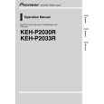
6. Multi-CD player 8. Note: (sold separately) Depending on kind of vehicle, the function 18. Connecting cords with RCA pin plugs sure connect 2* 5* and 4* to 3*. (sold separately) 1. This Product 4. IP-BUS cable 2. Rear output 5* 4* 20. Blue/white 12 V DC). 21. System remote control When not using this terminal, To Auto-antenna relay control terminal (max. 300 mA 12 V DC). 10. Cap (1*) 5. IP-BUS input (Blue) 7. Fuse 3. Antenna jack (sold separately)
1
type of vehicle, never connect 6* and 7*. 25. Left 26. Right ON/OFF. 27. Rear Speaker 28. Perform these connections when using 17. Speaker leads White : Front left + White/black : Front left â� the optional amplifier. Gray : Front right + Gray/black : Front right â� + â� + â�
1
of 3* and 5* may different. In this case, be
1*
3* 2* 19. Power amp
9. Connect leads of the same To system control terminal of
color to each other . the power amp (max. 300 mA
2
2
do not remove the cap. 22. Blue/white (7*)
11. (3*) 12. Yellow (2*) 23. Blue/white (6*)
KEH-P2033R/XM/EW
Back-up To terminal always supplied 24. The pin position of the ISO connector will differ (or accessory) with power regardless of depends on the type of vehicle. Connect 6* and 7*
ignition switch position. when Pin 5 is an antenna control type. In another
13. (5*) 14. Red (4*)
Accessory To electric terminal controlled (or back-up) by ignition switch (12 V DC)
3
3
15. Black (ground)
To vehicle (metal) body.
4
4
16. ISO connector Green : Rear left
Note: Green/black : Rear left In some vehicles, the ISO connector may be Violet : Rear right divided into two. In this case, be sure to Violet/black : Rear right connect to both connectors.
|
|
|
> |
|