|
|
|
Categories
|
|
Information
|
|
Featured Product
|
|
|
 |
|
|
There are currently no product reviews.
 ;
5 STARS for FAST DELIVERY, BEST PRICES and QUALITY PRODUCT. Item was exactly as described with superb resolution. Will definitely source all my future requirements from this website. Thanks a lot owner-manual.com!
;
OEM manual provided all schematics, board layouts and component specs necessary to facilitate unit maintenance. All pages were clear and readable.
;
Good condition and quality. Hard to find anywhere in Internet, only on this site.
 ;
Exactly what I needed to be able to bring the amp back to life... will come back to this site the next time I need schematics.
;
Information was accurate and very helpful.
However the continuity made it a little difficult to follow from one page to the next.
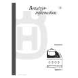
16.Connecting cords with RCA pin plugs (sold separately) 1.This Unit 19.To system control terminal 2.Rear output of the power amp or Auto15.Fuse nal.(Max. 300 mA 12 V DC) 3.Antenna jack 4.Multi-CD player white 18.System remote control (sold separately) 20.Power amp (sold separately) 7 Note: 6. Depending on kind of vehicle, the function of and 11 may be different. 9 8 If this is the case, be sure to connect 8 11 and 9 to 10. When the power cord of a 11 10 component such as a Multi-CD Player is connected to this unit's power 21.Left 22.Right speaker cord, check that 9 and 11 (Back-up or + color to each other. and that connections are correct. 23.Rear 7.Cap 8.Yellow â� 17.Blue/ antenna relay control termi-
5.Connect leads of the same Accessory) are operating correctly,
9.Yellow To terminal always supplied with power Back-up (or accessory) regardless of ignition switch position. 10.Red when you have the separately available amplifier. 12.Black (ground) To vehicle (metal) body.
11.Red To electric terminal controlled by ignition Accessory (or Back-up) switch (12 V DC) ON/OFF. 24.Use this for connections
13.ISO connector Note: In some vehicles, the ISO connector may be 14.Speaker leads divided into two. If this is the case, be sure to White: Front left + connect to both connectors. White/black: Front left â� Gray: Front right + Gray/black: Front right â� Green: Rear left + Green/black: Rear left â� Violet: Rear right + Violet/black: Rear right â�
> CAUTION
� Cords this product and those for other products may be different colors even if they have the same function. When connecting this product to another product, refer to the supplied Installation manuals of both products and connect cords that have the same function.
KEH-P2800R,P2830R,P28R
47
|
|
|
> |
|