|
|
|
Categories
|
|
Information
|
|
Featured Product
|
|
|
 |
|
|
There are currently no product reviews.
 ;
Great manual, great price. Has a few of the basic operating instructions that most service manuals leave out. Complete instructions for disassembling board by board, safety precautions, schematics, complete parts list.
;
I am very pleased with the service manual for my RT-909. This was an easy purchase and great procuct, and much cheaper than other venues i had looked at. This web site is now listed in my favorites list. KEEP UP THE GOOD WORK. THANKS. J. BROWN
;
A very well written and easy to understand manual.
;
There was no problem at all.After paying i had to wait only a few hours,than i could
download the manual in best pdf-quality.
Thank You !
 ;
I found this service manual to be complete in every detail except for troubleshooting charts. It would be helpful if it had a set of troubleshooting charts; however it is a very good manual otherwise and for the price it is very well worth it.
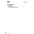
16.Connecting cords with RCA pin plugs (sold separately) 1.This Unit 19.To system control terminal 2.Rear output of the power amp or Auto15.Fuse nal.(Max. 300 mA 12 V DC) 3.Antenna jack 4.Multi-CD player white 18.System remote control (sold separately) 20.Power amp (sold separately) 7 Note: 6. Depending on kind of vehicle, the function of and 11 may be different. 9 8 If this is the case, be sure to connect 8 11 and 9 to 10. When the power cord of a 11 10 component such as a Multi-CD Player is connected to this unit's power 21.Left 22.Right speaker cord, check that 9 and 11 (Back-up or + color to each other. and that connections are correct. 23.Rear 7.Cap 8.Yellow â� 17.Blue/ antenna relay control termi-
5.Connect leads of the same Accessory) are operating correctly,
9.Yellow To terminal always supplied with power Back-up (or accessory) regardless of ignition switch position. 10.Red when you have the separately available amplifier. 12.Black (ground) To vehicle (metal) body.
11.Red To electric terminal controlled by ignition Accessory (or Back-up) switch (12 V DC) ON/OFF. 24.Use this for connections
13.ISO connector Note: In some vehicles, the ISO connector may be 14.Speaker leads divided into two. If this is the case, be sure to White: Front left + connect to both connectors. White/black: Front left â� Gray: Front right + Gray/black: Front right â� Green: Rear left + Green/black: Rear left â� Violet: Rear right + Violet/black: Rear right â�
> CAUTION
� Cords this product and those for other products may be different colors even if they have the same function. When connecting this product to another product, refer to the supplied Installation manuals of both products and connect cords that have the same function.
KEH-P2800R,P2830R,P28R
47
|
|
|
> |
|