|
|
|
Categories
|
|
Information
|
|
Featured Product
|
|
|
 |
|
|
There are currently no product reviews.
 ;
I have never bought a service manual which is as competely readable as this althogh it was a scanned pdf. Thank you for this succesful manual also cheaper than other sites.
;
Thanks for a very good and readable servicemanual. Just what I needed as a "dinosaur technician". I really recommmend this site and will come back.
Åsbjörn
;
The manual I purchased was just what I needed. I was glad to find a site where I can find so many manuals on a wide variety of products.
;
The best diagram that I used in a long time. Everything was right on te money. It was easy and fast. Iwoiuld but again when I need a service manual.
;
The manual is great help for me, i'm happy to have it,thanks
KEH-P424,P4700,P4750
7.2 DISASSEMBLY
- Removing the Case(not shown) 1. Remove the three screws. 2. Remove the Case. - Removing the Cassette Mechanism Module
(not shown)
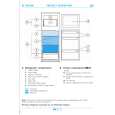
1. Remove the four screws. 2.Disconnect the connector, and then removing the Cassette Mechanism Module. - Removing the Detach Grille Assy(Fig.22) 1. Push the detach button. 2. Remove the Detach Grille Assy. - Removing the Panel Unit(Fig.22) 1. Disengage the stopper at four locations indicated by white-arrows and then remove the Panel. 2. Disengage the stopper at two locations indicated by black-arrows. 3. Remove the Panel Unit.
Fig. 22
- Removing the Tuner Amp Unit(Fig.23) 1. Removing the two screws A, three screws B and screw C. 2. Unbend the tabs at four locations indicated by arrow until straight. 3. Remove the Tuner Amp Unit.
Fig. 23
42
|
|
|
> |
|