|
There are currently no product reviews.
 ;
Excellent manual. Helped me out with disassembling and troubleshooting my projector.
;
thanks you are the best.Very good detail, Quick service response. A useful service manual with all details.
;
Great service!!! Polecam gorąco wszystkim zainteresowanym
;
I liked the price plus it had everything i needed to service the tv.
thankyou Tim Hertz
;
The manual is excellent, well detailed, and divided into two parts. Received very quickly. Thank you.
5. ADJUSTMENT
Refer to the figure in the next page and 10-2. Power supply.
5-1. Setting the thermal head
Perform this setting after removing batteries and AC adapter. After replacing the thermal head or chassis ass�y, decide to connect or not to connect RANK1 pads on the PCB ASSY with soldering according to the following table. Marking on the thermal head A B RNK1 pads connect (short) not connect (open)
5-2. Adjustment for power supply voltage to LCD
Be sure to perform this adjustment after replacing PCB ASSY, LCD, chassis ass�y and so on. 1 After supplying the voltage 12.5 V ± 2 % to SUM + terminal for battery, turn on the unit. 2 Adjusting VR1, set the voltage between CPVDD and CPV5 pads on the PCB ASSY to the voltage shown to the following table. Voltage between CPVDD and CPV5 pads Polarity: CPVDD (=VDD1) ¡ + (plus) CPV5 ¡ � (minus) 6.2 V ± 0.1 V
5-3. Adjustment for VP terminal voltage
Be sure to perform this adjustment after replacing PCB ASSY, motor, thermal head, chassis ass�y and so on. After supplying the voltage 12.5 V ± 2 % to SUM + terminal for battery, perform this adjustment while printing. Adjusting VR201, set the voltage between VP and CPD203 pads on the PCB ASSY to the voltage shown to the following table.
Voltage between VP and CPD203 Polarity: VP ¡ + (plus) CPD203 (=DGND) ¡ � (minus)
6.8 V ± 0.05 V
�8�
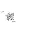 $4.99 KL8100 CASIO
Owner's Manual Complete owner's manual in digital format. The manual will be available for download as PDF file aft…
|