|
|
|
Categories
|
|
Information
|
|
Featured Product
|
|
|
 |
|
|
There are currently no product reviews.
 ;
It is perfect, exactly what we needed. It's like the paper version but less clutter.
 ;
Received my manual within 24 hours. Very clear scan of the manual I needed. Thanks!
;
Very clear scan, I recommend it. Definitely a must have for any 3362 owner.
Alpine could have written a slightly more complete manual, though. It's already pretty huge, but the unit has so many functions, I feel some more explanation would have been better.
Yamaha's manual of their comparable YDSP-1 is a little better in my opinion.
;
Immediate response with excellent service - highly reccommended
;
Correct manual received and of good quality but the contents of the file for the Service Manual for the same monitor is for a 20" TV not the RGB Monitor.
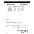
KP-53HS10/61HS10
RM-Y902 RM-Y902
3-5. FOCUS VR ADJUSTMENT
1. Set to the service mode. 2. Receive the all-white signal. 3. Cover the both red and blue picture lenses with the lens caps to show only the green color. 4. Set to PJE, and press 6 to display the test signal (crosshatch) on the screen. 5. Turn the green focus VR on the focus block to adjust to the optimum focus point with the test signal. 6. Cover the both green and blue picture lenses with the lens caps to show only the red color. 7. Set to PJE, and press 6 to display the test signal (crosshatch) on the screen. 8. Turn the red focus VR on the focus block to adjust to the optimum focus point with the test signal. 9. Cover the both green and red picture lenses with the lens caps to show only the blue color. 10. Set to PJE, and press 6 to display the test signal (crosshatch) on the screen. 11. Turn the blue focus VR on the focus block to adjust to the optimum focus point with the test signal. 12. After adjusting the items 3-4. Focus Lens Adjustment, 3-6. 2Pole Magnet Adjustment and 3-7. 4-Pole Magnet Adjustment, adjust again to the optimum focus point. Note: Instead of items 3, 6 and 9, you can cut off the unnecessary color beams by controlling the service mode MCP1 07 RON, 08 GON, and 09 BON.
Scanning line visible.
Use the center dot
Fig. 3-7
3-7. 4-POLE MAGNET ADJUSTMENT
1. Receive the Dot signal. 2. Set in service mode. 3. Cover the both red and blue picture lenses with the lens caps to show only the green color. 4. Turn the green focus VR on the focus block to the left and set to underfocus to enlarge the spot. 5. Now align the 4-Pole Magnet so that the enlarged spot becomes a perfect circle for green and red. 6. Perform the same alignment for blue.
Use the center dot
x
/
y x : y = 1:1.5 (BIue) x : y = 1:1 (Green, Red)
Fig. 3-8
3-8. DEFOCUS ADJUSTMENT (BLUE)
A Minimize both A and B.
Note: Please adjust the blue dot to be slightly larger than red and green dots. This adjustment provides a more pleasing picture to the customer. 1. Select the video menu and set the mode to �VIVID� mode. 2. Set to the service mode.
Lens Fig. 3-5
B Center of crosshatch
Fig. 3-6
3. Change TV mode to the video input mode. 4. Set to PJE, and press 6 to display the test signal (dots) on the screen. 5. Turn the blue focus VR on the focus block to adjust to the diameter of the dots as shown in the figure below. [Focus adjustment point]
3-6. 2-POLE MAGNET ADJUSTMENT (GREEN,RED)
1. Receive the Dot signal. 2. Set in service mode. 3. Cover the both red and blue picture lenses with the lens caps to show only the green color. 4. Turn the green focus VR on the focus block to the right and set to overfocus to enlarge the spot. 5. Now align the 2-Pole Magnet so that the enlarged spot is in the center of the Just Focus spot. 6. Align the green focus VR and set for just (precise) focus. 7. Perform the same alignment for red.
Lmm Max
Inch L 53" 8 61" 9
Fig. 3-9
� 42 �
|
|
|
> |
|