|
|
|
Categories
|
|
Information
|
|
Featured Product
|
|
|
 |
|
|
There are currently no product reviews.
 ;
Everything you need: schematic, circuit explanation, operating/testing instructions. Awesome.
 ;
Correct and accurate service manual for that Siemens (Nordmende) TV. Price is worthwhile as the Manual is fully usable.
;
Just what I needed to repair my CT-F600, clear pdf, easy to tread and navigate
;
Yes, cost is low. And quality of some diagrams is low too.
;
Quick response.
Good quality.
Not large price of documents.
Thanks.
Dzięki.
KP-53XBR300/61XBR300
RM-Y902 RM-Y902
SECTION 3 SET-UP ADJUSTMENTS
*: Every time you press 6, the test signal changes to �crosshatch+video signal� - �dots+video signal� �crosshach(black)� - �dots(black)� - off. Note: Instead of items 4, 8 and 11, you can use the lens caps to cut off the unnecessary color beams.
3-1. SCREEN VOLTAGE ADJUSTMENT (ROUGH ALIGNMENT)
1. Receive the Monoscope signal. 2. Set 50% BRIGHTNESS and minimum PICTURE. 3. Turn the red VR on the FOCUS block all the way to the left and then gradually turn it to the right until the point where you can see the retrace line. 4. Next gradually turn it to the left to the position where the retrace line disappears.
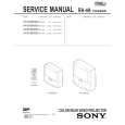
R G SCREEN R G FOCUS B B
3-3. SCREEN (G2) ADJUSTMENT
1. Select VIDEO1 mode without signals. 2. Connect an oscilloscope to the TP7103(KR), TP7203(KG) and TP7303(KB) of CR board, CG board and CB board. 3. Adjust R, G and B screen voltage to 175 ± 2V with screen VR on the Focus block.
175 ± 2V
pedestal level
FOCUS block
Fig. 3-1
GND
3-2. FOCUS LENS ADJUSTMENT
In this adjustment, use the remote commander in the service mode. For details of the usage of the service mode and the remote commander, please refer the item 3-9. ELECTRICAL ADJUSTMENT BY REMOTE COMMANDER. 1. Loosen the lens screw. 2. Set to the service mode. 3. Receive the all-white signal. 4. Set MCP1 07 RON to �000�, 08 GON to �001� and 09 BON to �000� to show only the green color. 5. Set to PJE, and press 6 to display the test signal (crosshatch)� on the screen. 6. Turn the green lens to adjust to the optimum focus point with the test signal. 7. Tighten the lens screw. 8. Set MCP1 07 RON to �001�, 08 GON to �000� and 09 BON to �000� to show only the red color. 9. Set to PJE, and press 6 to display the test signal (crosshatch)� on the screen. 10. Adjust red CRT lens just the same as green. 11. Set MCP1 07 RON to �000�, 08 GON to �000� and 09 BON to �001� to show only the blue color.
Fig. 3-3
3-4. FOCUS VR ADJUSTMENT
1. Set to the service mode. 2. Receive the all-white signal. 3. Set MCP1 07 RON to �000�, 08 GON to �001� and 09 BON to �000� to show only the green color. 4. Set to PJE, and press 6 to display the test signal (crosshatch) on the screen. 5. Turn the green VR on the focus block to adjust to the optimum focus point with the test signal. 6. Set MCP1 07 RON to �001�, 08 GON to �000� and 09 BON to �000� to show the red color. 7. Set to PJE, and press 6 to display the test signal (crosshatch) on the screen. 8. Turn the red VR on the focus block to adjust to the optimum focus point with the test signal. 9. Set MCP1 07 RON to �000�, 08 GON to �000� and 09 BON to �001� to show the blue color. 10. Set to PJE, and press 6 to display the test signal (crosshatch) on the screen. 11. Turn the blue VR on the focus block to adjust to the optimum focus point with the test signal. Note: Instead of items 3, 6 and 9, you can use the lens caps to cut off the unnecessary color beams.
Scanning line visible.
Test signal Fig. 3-2 12. Set to PJE, and press 6 to display the test signal (crosshatch)� on the screen. 13. Adjust blue CRT lens just the same as green. Lens Fig. 3-4
B
A Minimize both A and B.
Center of crosshatch
Fig. 3-5
� 42 �
|
|
|
> |
|