|
|
|
Categories
|
|
Information
|
|
Featured Product
|
|
|
 |
|
|
There are currently no product reviews.
 ;
Great price for the manual and easy to locate on the site and download. I would buy again.
 ;
Very good copy of Manual, clear and easy to print off, arrived very promptly and reasonably priced. Thanks, I will use you again
;
The service manual when downloaded and printed out was clear and easy to read. The manual is complete with the schematic diagram and technical data. I occasionally require a manual and now having registered with this company I shall order from them in the future.
;
Great manual, great price. I am very pleased with Owner-Manuals.com, quick service, fast communication. Will definitely use this site again.
;
Hello from Germany - thank you very much for the manual for my Sharp "Searcher" - the handling of your internet area is outstanding..Mike
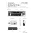
Connecting Cables to Terminals
Connecting the ISO Connector (see p.24) The pin arrangement for the ISO connectors depends on the type of vehicle you drive. Make sure to make the proper connections to prevent damage to the unit. The default connection for the wiring harness is described in 1 below. If the ISO connector pins are set as described in 2 or 3, make the connection as illustrated. 1 (Default setting) The A-7 pin (red) of the vehicle's ISO connector is linked with the ignition, and the A-4 pin (yellow) is connected to the constant power supply. Unit Vehicle Ignition cable (Red) A�7 Pin (Red) Battery cable (Yellow) A�4 Pin (Yellow)
2WARNING
Installation s Installation
Firewall or metal support
Accessory3
Bend the tabs of the mounting sleeve with Self-tapping screw (commercially available)
NOTE
2 The A-7 pin (red) of the vehicle's ISO connector is connected to the constant power supply, and the A-4 pin (yellow) is linked to the ignition. Unit Vehicle Ignition cable (Red) A�7 Pin (Red) Battery cable (Yellow) A�4 Pin (Yellow)
Metal mounting strap (commercially available)
a screwdriver or similar utensil and attach it in place.
Make sure that the unit is installed securely in place. If the unit is unstable, it may malfunction (eg, the sound may skip).
3 The A-4 pin (yellow) of the vehicle's ISO connector is not connected to anything, while the A-7 pin (red) is connected to the constant power supply (or both the A-7 (red) and A-4 (yellow) pins are connected to the constant power supply). Unit Vehicle Ignition cable (Red) A�7 Pin (Red) Battery cable (Yellow)
NOTE
A�4 Pin (Yellow)
When the connection is made as in 3 above, the unit's power will not be linked to the ignition key. For that reason, always make sure to turn off the unit's power when the ignition is turned off. To link the unit's power to the ignition, connect the ignition cable (ACC...red) to a power source that can be turned on and off with the ignition key.
� 25 �
|
|
|
> |
|