|
|
|
Categories
|
|
Information
|
|
Featured Product
|
|
|
 |
|
|
There are currently no product reviews.
 ;
Yes thank you i got the file i was after. There was a slight problem in my communication but it all worked out well.
A job well done.
 ;
Great manual...really saved me. The only problem is that I thought I would be able to download it directly when I paid for it but never received the download instructions until the next morning. The board trace pages were somewhat light also: really need to turn up the contrast on the printer before printing them. The schematic page was great; very clear! Well worth the money.
;
I've been in the electronic business for a long time. I used to buy Sam's Photofact for my needs which intailed having to go to the store and paying about $20 for a package of 3 different units so I was forced to buy more than I needed just to get one.
Owner manual is just at your keyboard and the information is almost instantansouly and the cost is very reasonable. Easy to print out if needed or simply read off of the screen. The larger the screen the better for obvious reasons.
;
Very good manual, at a very good price. Received in a timely manner
;
Only thу cover has poor quality, internal material has excellent quality - exactly what I needed
Thanks!
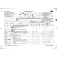
KRF-V6060D/V7060D/V8060D/X9060D/VR-6050/6060/6070
CIRCUIT DESCRIPTION
6-3 96kHz 24Bit DIR : AK4112BVF (X08, IC2)
Pin No. 1 2 3 4 5 6 7 8 9 10 11 12 13 14 15 16 17 18 19 20 21 22 23 24 25 26 27 28 Pin Name DVDD DVSS TVDD TX XTI XTO PDN R AVDD AVSS RX1 RX2 RX3 RX4 AUTO P/S FS96 ERF LRCK SDTO BICK DAUX MCK02 MCK01 CSN CCLK CDTI CDTO I/O O I O I I I I I O I O O I/O O I/O I O O I I I O Pin Description Digital power supply pin. (3.3V) Digital ground pin. Input buffer power supply pin. (5.0V) Transmit channel (through data) output pin in serial mode. X'tal input pin. X'tal output pin. (Open) Power down mode pin. When "L", the AK4112B is powered-down and reset. External resistor pin. Analog power supply pin. Analog ground pin. Receiver channel 1 This channel is selected in parallel mode or default of serial mode. Receiver channel 2 in serial mode. Receiver channel 3 in serial mode. Receiver channel 4 in serial mode. Non PCM detect pin. "L" : No detect, "H" : Detect (Open) Parallel/Serial select pin. "L" : Serial mode, "H" : Parallel mode (Analog ground) 96kHz sampling detect pin. (RX Mode) "H" : fs=88.2kHz or more, "L" fs=54kHz or less. (X'tal Mode) "H" : XFS96=1, "L" : XFS96=0. Unlock & Parity Error output pin. "L" : No error, "H" : Error Output channel clock pin. Audio serial data output pin. Audio serial data clock pin. Auxiliary audio data input pin. (Analog ground) Master clock #2 output pin. (Open) Master clock #1 output pin. Chip select pin in serial mode. Control data clock pin in serial mode. Control data input pin in serial mode. Control data output pin in serial mode.
6-4 96kHz 24Bit CODEC & DAC : AK4529-VQ (X08, IC4)
Pin No. 1 2 3 4 5 6~8 9 10 11 12 13 14 15 16 17 18 19 20 21 22 23 24 Pin Name SDOS I2C SMUTE BICK LRCK SDTI (1~3) SDTO DAUX DFS SDTI4 DZFE TVDD DVDD DVSS PDN TST CAD1 CAD0 LOUT4 ROUT4 LOUT3 ROUT3 I/O I I I I I I O I I I I O O O O Pin Description SDTO Source Select Pin (unused) Control Mode Select Pin (unused) Soft Mute Pin (Unused) Audio Serial Data Clock Pin Input Channel Clock Pin DAC(1~3) Audio Serial Data Input Pin Audio Serial Data Output Pin AUX Audio Serial Data Input Pin (GND) Double Speed Sampling Mode Pin (GND) DAC4 Audio Serial Data Input Pin (GND) Zero Input Detect Enable Pin (GND) Output Buffer Power Supply Pin (+3.3V) Digital Power Supply Pin (+5.0V) Digital Ground Pin Power Down & Reset Pin Test Pin (GND) Chip Address 1 Pin (GND) Chip Address 0 Pin DAC4 Center Channel Output Pin DAC4 SW Channel Output Pin DAC3 SBL Channel Output Pin DAC3 SBR Channel Output Pin
9
|
|
|
> |
|