|
|
|
Categories
|
|
Information
|
|
Featured Product
|
|
|
 |
|
|
There are currently no product reviews.
 ;
Great Manual! It contains all the wiring schematics and mechanical exploded views that are essential for service and repair. I was surprised I even found this for such an old machine. Only wish I knew of this site many years ago.
;
Great manual very clear copied. You are making an incredible job. I appreciate a lot the rapidity and your efficiency. Thanks a lot
;
Good pdf of the service manual for this unit. Includes disassembly instructions, full schematics, board layouts, parts lists and diagnostic information. Some information is in the pdf twice (single pages, and split pages), but that could be how it was originally generated by panasonic, or perhaps the idea is to make it eaiser to put onto 8.5 x 11" pages.
Information was exactly what I needed. Delivery was overnight (less than 12 hours) and I was happy with the process.
;
5 STARS for FAST DELIVERY, BEST PRICES and QUALITY PRODUCT. Item was exactly as described with superb resolution. Will definitely source all my future requirements from this website. Thanks a lot owner-manual.com!
;
OEM manual provided all schematics, board layouts and component specs necessary to facilitate unit maintenance. All pages were clear and readable.
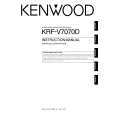
KRF-V7070D/V8070D/X9070D/VR-7060/7070/7080
EXTERNAL VIEW / ADJUSTMENT
EXTERNAL VIEW
Knob (K29-8107-02) Panel * (A60-) Knob ass'y * (K29-) Front glass * (B10-) Knob ass'y * (K29-) Knob * (K29-)
VOLUME CONTROL POWER
STANDBY
THX SPEAKER EQ
ON/STANDBY
DOLBY DIGITAL DTS CS II DSP STEREO INPUT MODE DIMMER
ACTIVE EQ THX
A SPEAKERS B
SPEAKER EQ ACTIVE EQ
DOWN MUTE DVD/6CH CD/DVD PHONO TUNER SOUND TONE
PHONES
UP
MULTI CONTROL SETUP
LISTEN MODE AV AUX S VIDEO VIDEO L-AUDIO-R
VIDEO 1
VIDEO 2
VIDEO 3
MD/TAPE BAND AUTO MEMORY
Phone jack (E11-0271-05)
Knob (K29-8111-02)
Knob * (K29-)
Pin jack (E63-1251-05) Cylindrical receptacle (E56-0033-05)
Illust. is VR-7060. * Refer to parts list on page 29 .
ADJUSTMENT
No. ITEM INPUT OUTPUT SETTINGS SETTINGS SPEAKER : A CN11, FL ch. CN10, FR ch. CN14, SL ch. CN13, SR ch. CN12, C ch. CN15, SW ch. X09(A/5) RECEIVER SETTINGS ALIGNMENT POINTS VR1(FL) VR2(FR) VR3(SL) VR4(SR) VR5(CENTER) VR6(SUB WOOFER) X09(A/5) ALIGN FOR FIG.
AUDIO SECTION
<1>
IDLE CURRENT
-
(FRONT 2ch MODE) Volume: Minimum
Adjust every potentiometer 10 minutes later after turned the power on.
Idling Current Adjustment All power amplifier stage need idling current adjustment after the installation of TRAIT transistor. 1. Connect a voltmeter to CN11 with the correct polarity as indicated by the PCB silk print. 2. Adjust the preset, VR1 to get 8.8mV (Idling current = 20mA) at the voltmeter reading. 3. Repeat step 1 and 2 for all other channels.
3
|
|
|
> |
|