|
|
|
Categories
|
|
Information
|
|
Featured Product
|
|
|
 |
|
|
There are currently no product reviews.
 ;
Excellent printing quality.
A complete and very usefull service manual with all details.
GREAT SERVICE AT VERY LOW PRICE!
A+++++++++++++++++++++++++
;
Thank you for providing quickly a manual so old! very good job clear and understandable!
;
Excellent printing quality.
A complete and very usefull service manual with all details.
GREAT SERVICE AT VERY LOW PRICE!
A+++++++++++++++++++++++++
;
Excellent printing quality.
A complete and very usefull service manual with all details.
GREAT SERVICE AT VERY LOW PRICE!
A+++++++++++++++++++++++++
;
Excellent printing quality.
A complete and very usefull service manual with all details.
GREAT SERVICE AT VERY LOW PRICE!
A+++++++++++++++++++++++++
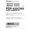
KRF-V7773D/V7773D-B/V9993D
DISASSEMBLY FOR REPAIR
HOW TO REMOVE THE FRONT PANEL AND THE MOTOR.
1. Take out the connectors (1) {X07,CN1/X13(CN7,CN8)} and the AC connetor(2). 2. Take the lead (3) out of CN301 on X11(A/4) PCB. 3. Take out the screws (4) and (5). 4. The front panel can be separated by removing 2 hooks (6) on the sub panel. 5. To separate the motor from the front panel, remove the screws (7).
MOTOR
2
AC CONNECTOR X07,CN1
1 7 x5 4 x5 4
1 1
X13
(G/8)
X25
CN8
CN7
H/P PCB
3
X11
(A/4)
CN301
6 x2 HOOK 5 x5 5
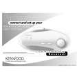
HOW TO REPLACE THE POWER TRANSISTOR.
1. The rear panel can be separated by removing screws (1) on the rear panel. 2. Take the AC connector out of CN2 on the X07(C/7). 3. To separate the chassis from bottom chassis, remove the screws (2). 4. Remove CN21 and screws (3) on X13(C/5). 5. Remove screws (4 to 7). 6. The fan motor can be separated by removing screws (8) and the connector (CN12) on X07 PCB. 7. Take the PCB X25(B/9), X11(C/4)} out of X07. 8. To separate the main PCB (X07) from the bottom chassis, remove screws (0). 9. Set up the PCB as figure (-). 10. Replace the defective transistors.
2 9 7 5
(C/9)
X25
X05-5130-11
4 7 x2 7 6 6
(C/5)
X13
CN21
3 x2 3 x2 8 x9
2
X07 CN12
2 2 2
2
2
X07-3150-10
(A/5)
11 10 10
CN2
10 10
10
CN14 CN6 X25
(B/9)
X07
(C/7)
X11
(C/4)
10 x3
4
1 x70
|
|
|
> |
|