|
|
|
Categories
|
|
Information
|
|
Featured Product
|
|
|
 |
|
|
There are currently no product reviews.
 ;
The schematic is very helpful and the images are very good.The schematic is very helpful and the images are very good.The schematic is very helpful and the images are very good.The schematic is very helpful and the images are very good.The schematic is very helpful and the images are very good.The schematic is very helpful and the images are very good.
;
Welcome. The scheme is clearly helped me to repair. Worth to download it.
 ;
Excellent manual, very clear, technical specification provided, useful information regarding adjustment and set up.
;
fast and easy and exactly what I was looking for. Not the cheapest but value for money after all.
;
The manual for the Sansui P-L75 was not one of the more informative turntable manuals around but for $5 it was helpful enough.
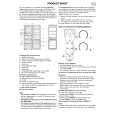
KRF-V6060D/V7060D/V8060D/X9060D/VR-6050/6060/6070
CIRCUIT DESCRIPTION
6-3 96kHz 24Bit DIR : AK4112BVF (X08, IC2)
Pin No. 1 2 3 4 5 6 7 8 9 10 11 12 13 14 15 16 17 18 19 20 21 22 23 24 25 26 27 28 Pin Name DVDD DVSS TVDD TX XTI XTO PDN R AVDD AVSS RX1 RX2 RX3 RX4 AUTO P/S FS96 ERF LRCK SDTO BICK DAUX MCK02 MCK01 CSN CCLK CDTI CDTO I/O O I O I I I I I O I O O I/O O I/O I O O I I I O Pin Description Digital power supply pin. (3.3V) Digital ground pin. Input buffer power supply pin. (5.0V) Transmit channel (through data) output pin in serial mode. X'tal input pin. X'tal output pin. (Open) Power down mode pin. When "L", the AK4112B is powered-down and reset. External resistor pin. Analog power supply pin. Analog ground pin. Receiver channel 1 This channel is selected in parallel mode or default of serial mode. Receiver channel 2 in serial mode. Receiver channel 3 in serial mode. Receiver channel 4 in serial mode. Non PCM detect pin. "L" : No detect, "H" : Detect (Open) Parallel/Serial select pin. "L" : Serial mode, "H" : Parallel mode (Analog ground) 96kHz sampling detect pin. (RX Mode) "H" : fs=88.2kHz or more, "L" fs=54kHz or less. (X'tal Mode) "H" : XFS96=1, "L" : XFS96=0. Unlock & Parity Error output pin. "L" : No error, "H" : Error Output channel clock pin. Audio serial data output pin. Audio serial data clock pin. Auxiliary audio data input pin. (Analog ground) Master clock #2 output pin. (Open) Master clock #1 output pin. Chip select pin in serial mode. Control data clock pin in serial mode. Control data input pin in serial mode. Control data output pin in serial mode.
6-4 96kHz 24Bit CODEC & DAC : AK4529-VQ (X08, IC4)
Pin No. 1 2 3 4 5 6~8 9 10 11 12 13 14 15 16 17 18 19 20 21 22 23 24 Pin Name SDOS I2C SMUTE BICK LRCK SDTI (1~3) SDTO DAUX DFS SDTI4 DZFE TVDD DVDD DVSS PDN TST CAD1 CAD0 LOUT4 ROUT4 LOUT3 ROUT3 I/O I I I I I I O I I I I O O O O Pin Description SDTO Source Select Pin (unused) Control Mode Select Pin (unused) Soft Mute Pin (Unused) Audio Serial Data Clock Pin Input Channel Clock Pin DAC(1~3) Audio Serial Data Input Pin Audio Serial Data Output Pin AUX Audio Serial Data Input Pin (GND) Double Speed Sampling Mode Pin (GND) DAC4 Audio Serial Data Input Pin (GND) Zero Input Detect Enable Pin (GND) Output Buffer Power Supply Pin (+3.3V) Digital Power Supply Pin (+5.0V) Digital Ground Pin Power Down & Reset Pin Test Pin (GND) Chip Address 1 Pin (GND) Chip Address 0 Pin DAC4 Center Channel Output Pin DAC4 SW Channel Output Pin DAC3 SBL Channel Output Pin DAC3 SBR Channel Output Pin
9
|
|
|
> |
|