|
|
|
Categories
|
|
Information
|
|
Featured Product
|
|
|
 |
|
|
There are currently no product reviews.
 ;
This is an excellent information source. Great quality and tons of info regarding technical service for the Technics SH8065.
;
5 stars on this manual since it is the complete version, not the half manual you find free for download all over the web. Good job.
;
Thank you very much you are helping me a lot with my preferred hobby!!! this manual of an old TV is going to be very helpful!!!!
You are very honest competent great job very clear and well done!!!!
Matteo
;
An excellent service manual contains dismantling locations of components, electronic adjustments,worth the money.
;
Caracteristiques,circuit adjusment,notes on schematis diagram,it's a good service manual,to live well,thanks.
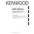
KRF-V7070D/V8070D/X9070D/VR-7060/7070/7080
EXTERNAL VIEW / ADJUSTMENT
EXTERNAL VIEW
Knob (K29-8107-02) Panel * (A60-) Knob ass'y * (K29-) Front glass * (B10-) Knob ass'y * (K29-) Knob * (K29-)
VOLUME CONTROL POWER
STANDBY
THX SPEAKER EQ
ON/STANDBY
DOLBY DIGITAL DTS CS II DSP STEREO INPUT MODE DIMMER
ACTIVE EQ THX
A SPEAKERS B
SPEAKER EQ ACTIVE EQ
DOWN MUTE DVD/6CH CD/DVD PHONO TUNER SOUND TONE
PHONES
UP
MULTI CONTROL SETUP
LISTEN MODE AV AUX S VIDEO VIDEO L-AUDIO-R
VIDEO 1
VIDEO 2
VIDEO 3
MD/TAPE BAND AUTO MEMORY
Phone jack (E11-0271-05)
Knob (K29-8111-02)
Knob * (K29-)
Pin jack (E63-1251-05) Cylindrical receptacle (E56-0033-05)
Illust. is VR-7060. * Refer to parts list on page 29 .
ADJUSTMENT
No. ITEM INPUT OUTPUT SETTINGS SETTINGS SPEAKER : A CN11, FL ch. CN10, FR ch. CN14, SL ch. CN13, SR ch. CN12, C ch. CN15, SW ch. X09(A/5) RECEIVER SETTINGS ALIGNMENT POINTS VR1(FL) VR2(FR) VR3(SL) VR4(SR) VR5(CENTER) VR6(SUB WOOFER) X09(A/5) ALIGN FOR FIG.
AUDIO SECTION
<1>
IDLE CURRENT
-
(FRONT 2ch MODE) Volume: Minimum
Adjust every potentiometer 10 minutes later after turned the power on.
Idling Current Adjustment All power amplifier stage need idling current adjustment after the installation of TRAIT transistor. 1. Connect a voltmeter to CN11 with the correct polarity as indicated by the PCB silk print. 2. Adjust the preset, VR1 to get 8.8mV (Idling current = 20mA) at the voltmeter reading. 3. Repeat step 1 and 2 for all other channels.
3
|
|
|
> |
|