|
|
|
Categories
|
|
Information
|
|
Featured Product
|
|
|
 |
|
|
There are currently no product reviews.
 ;
Superb rendition. Drawings (schematics) complete and unabridged. I do a great deal of vintage audio restoration. Documentation is essential for successful repairs. I have found sources over the years that offer good documentation, but rarely all that is necessary. Owner's Manuals has filled that void with complete and legible documentation. They have narrowed my "favorites" to a more manageable collection. This Denon manual in particular contained the latest revisions level, and offered alterations favorable to updating the item. The Illustrated Parts Breakdown (IPB) was well enough detailed to simplify part symbols and physical locations. You will not be disappointed!
;
Clear and concise. Saved me a lot of time and money.
;
Superb manual. Exactly what I ordered and made available in a very timely manner.
 ;
very fast detailed and accurate hope to do business again
;
This was precisely what I was looking for. Complete and good quality!
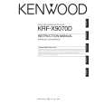
KRF-V7070D/V8070D/X9070D/VR-7060/7070/7080
EXTERNAL VIEW / ADJUSTMENT
EXTERNAL VIEW
Knob (K29-8107-02) Panel * (A60-) Knob ass'y * (K29-) Front glass * (B10-) Knob ass'y * (K29-) Knob * (K29-)
VOLUME CONTROL POWER
STANDBY
THX SPEAKER EQ
ON/STANDBY
DOLBY DIGITAL DTS CS II DSP STEREO INPUT MODE DIMMER
ACTIVE EQ THX
A SPEAKERS B
SPEAKER EQ ACTIVE EQ
DOWN MUTE DVD/6CH CD/DVD PHONO TUNER SOUND TONE
PHONES
UP
MULTI CONTROL SETUP
LISTEN MODE AV AUX S VIDEO VIDEO L-AUDIO-R
VIDEO 1
VIDEO 2
VIDEO 3
MD/TAPE BAND AUTO MEMORY
Phone jack (E11-0271-05)
Knob (K29-8111-02)
Knob * (K29-)
Pin jack (E63-1251-05) Cylindrical receptacle (E56-0033-05)
Illust. is VR-7060. * Refer to parts list on page 29 .
ADJUSTMENT
No. ITEM INPUT OUTPUT SETTINGS SETTINGS SPEAKER : A CN11, FL ch. CN10, FR ch. CN14, SL ch. CN13, SR ch. CN12, C ch. CN15, SW ch. X09(A/5) RECEIVER SETTINGS ALIGNMENT POINTS VR1(FL) VR2(FR) VR3(SL) VR4(SR) VR5(CENTER) VR6(SUB WOOFER) X09(A/5) ALIGN FOR FIG.
AUDIO SECTION
<1>
IDLE CURRENT
-
(FRONT 2ch MODE) Volume: Minimum
Adjust every potentiometer 10 minutes later after turned the power on.
Idling Current Adjustment All power amplifier stage need idling current adjustment after the installation of TRAIT transistor. 1. Connect a voltmeter to CN11 with the correct polarity as indicated by the PCB silk print. 2. Adjust the preset, VR1 to get 8.8mV (Idling current = 20mA) at the voltmeter reading. 3. Repeat step 1 and 2 for all other channels.
3
|
|
|
> |
|