|
|
|
Categories
|
|
Information
|
|
Featured Product
|
|
|
 |
|
|
There are currently no product reviews.
 ;
Good-quality scans. Detailed description. I hope I can repair the machine.
;
High-quality scanning. Detailed description. Recommend for all technician. A+++
;
This is a good quality scan of the original Service Manual from Nordmende, Germany. Contains the circuit diagram, PCB layout, adjust/tune instructions as well. It is NOT in English but in GERMAN language! That was quite right for my german friend from the lower east side in Berlin.
 ;
Received via e-mail this PDF manual is worth the money. This is a quality scan of a manual in excellent condition and is just as good as having the original manual in hand. I have later seen the original manual and it was printed in colour, but this particular manual is black & white but scan resolution is high end quality! All drawings and pictures are presented in great detail. So, nearly perfect score in my opinion.
If you own the turntable you also should own the manual!
;
I was very satisfied with the service manual I ordered and downloaded. I will definitely buy again from this seller.
KS-AX4700
Removal of main parts
CAUTION: If electricity is connected during disassembly, it must be a no load current. If it is load current, be sure to attach a heat sink to the power-amp IC. This will be damaged if the above precautions are not followed, as it does not have a sub heat sink attached to it.
B
Bottom cover
Removing the bottom cover (see Fig. 1)
1. From the bottom side of the main unit, remove the 4 screws A retaining the bottom cover. 2. Then remove the 6 screws B retaining the bottom cover. 3. Remove the bottom cover.
A
A
B
Fig. 1
Top panel
Removing the MAIN PCB (see Fig. 2 to 8)
1. Remove the bottom cover from the main unit. 2. Loosen and remove the 2 screws C retaining the top plate on the main unit. (Stoppers are attached to the backs of the C screws so that they cannot be removed easily.)
C
C
Fig. 2
3. Remove the 6 volume knobs on top of the control panel. If it cannot be pulled out easily, insert a rope or wire between the base of the volume knob and the control panel so that the volume knob is raised a little above the surface and then remove it. (Be careful when inserting a lever etc. not to scratch the surface of the control panel). 4. Remove the 4 screws D retaining the control panel. Then detach the control panel and the switch knobs.
Volume knob
D
Switch knob Control panel
D
Fig. 3
Volume knob
Rope or wire Control panel
(Side view)
Fig. 4
1-5
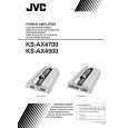 $4.99 KSAX4700 JVC
Owner's Manual Complete owner's manual in digital format. The manual will be available for download as PDF file aft…
|
|
|
> |
|