|
|
|
Categories
|
|
Information
|
|
Featured Product
|
|
|
 |
|
|
There are currently no product reviews.
 ;
El producto satisface las necesidades del servicio t
;
This is a good quality scan of the Operation & Maintenance (Service) Manual for the PAL version of this high-band broadcast umatic, BVU-800P
All schematics and lineup procedures appear to be included in this one manual AFAICT.
The file size is just over 113 MB which gives an idea of the quality and number of pages.
All of the schematics, which contain some fairly small print, are easily readable when you zoom into the page.
John Thompson, Newcastle Upon Tyne, England.
;
Good quality, all schematics of few of models. There is also short form of user manual and regulation manual.
;
Perfect copy of the service manual. you can enlarge every page, and it comes up
with all details.
;
It´s very very nice manual with all, what i need. Original in good quality. Very fast business. Very much thanks...
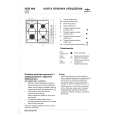
KS-FX473R/KS-FX470R
Pinch-roller (R) assembly S support plate C washer A arm spring (b) Shaft Pinch-roller (F) assembly
D
A arm spring (a) Shaft
FF roller
Playback head
Remove the P arm spring (r) from the chassis.
Remove the P arm spring (f) from the chassis.
P arm spring (r)
P arm spring (f)
Fig.2
Removing the playback head (See Fig.2)
Prior to performing the following procedure, remove the direction switch board and the FF / REW lever assembly. 1. Remove the screw D attaching the playback head. 2. Remove the C washer and pull out the FF roller. 3. Remove the S support plate, the A arm spring (a) and (b), the playback head. ATTENTION: The A arm spring (a) differs from the A arm spring (b).
Removing the pinch-roller (R) and (F) assembly (See Fig.2)
Prior to performing the following procedure, remove the direction switch board and the FF / REW lever assembly. 1. Remove the P arm spring (f) in the pinch-roller (F) assembly from the chassis. 2. Remove the P arm spring (r) in the pinch-roller (R) assembly from the chassis. 3. Draw out the pinch roller (F) and (R) assembly from the shaft. ATTENTION: The P arm spring (f) differs from the P arm spring (r). ATTENTION: The pinch roller (F) assembly differs from the pinch roller (R) assembly.
1-9
|
|
|
> |
|