|
|
|
Categories
|
|
Information
|
|
Featured Product
|
|
|
 |
|
|
There are currently no product reviews.
 ;
Very pleased with manual except that a few more details in the drawings might make the job (not yet done, tut-tut) easier. Should be adequate though. Actually I didn't have to pay for this anyway as I was given credit for another item that wasn't quite complete. Good service, then.
;
Very useful manuals, somewhere graphics not very clear!
 ;
A great manual; it contained all the information I required and allowed me to restore the receiver to full working condition!
;
Very good expirience with owner-manuals.com.
5 Stars; In future if necessary, i´ll download manuals on this site.
;
Hi - happy with what I received but not quite what I wanted - my fault I assumed that service manual would also include operational instructions which is what I needed - all I needed to know was how to turn the radio - thanks
KS-FX742R
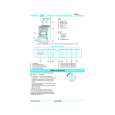
2.2.13 Removing the gear base arm / gear base link assembly (See Fig.25 to 27) (1) Move the gear base arm in the direction of the arrow. (2) Insert a slotted screwdriver to the gear base spring under the gear base arm, and release the gear base arm upward from the boss on the gear base assembly. (3) Remove the gear base arm from the main chassis while releasing the two joints s. (4) Move the gear base link assemby in the direction of the arrow to release the two joints t. REFERENCE: When reattaching the gear base arm, make sure that the boss on the gear base assembly is inside the gear base spring.
Joint t
Joints Gear base arm s
Hook u FFC pad Hook u
Gear base link assembly
Joint t Fig.25
Gear base spring
Gear base arm Screwdriver
Fig.26 2.2.14 Removing the FFC pad (See Fig.27 and 29) (1) Push each joint hook u of the FFC pad and remove toward the bottom.
Gear base link assembly
Gear base arm
FFC pad
Fig.27
1-12 (No.49816)
|
|
|
> |
|