|
|
|
Categories
|
|
Information
|
|
Featured Product
|
|
|
 |
|
|
There are currently no product reviews.
 ;
This is a high quality manual with clear schematic and components layout diagrams ; with service procedure included.
 ;
This service manual for the Kenwood KT-990D was reproduced really well ,is very legible and manual is complete.Combined with the low price paid,in the future,I will be checking Owner-Manuals.com any time I need a manual.
;
When I purchased this manual I had my doubts regarding the quality as the price was so reasonable as compared to other outlets.
The manual itself is of high standard the print is very clear as are the diagrams. Obviously with the diagrams one has to zoom in otherwise it is to small to be able to read.
Overall I am very pleased with the company who delivered as they said and with the manual they supplied.
I occasionally require a manual and now having registered with this company I shall order from them in the future.
;
I was at first dubious about payiong for downloaded manuals but having done so, I was extremely impressed with quality of the two manual I ordered, well worth the small price I paid.
I would highly recommend these to my friends.
;
reasonable price for the schematic - the service is perfect, all as expected and pointed by instructions - good scan of the original plans - thank you!
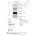
KS-FX901/KS-FX801
Cassette mechanism ass�y
<Removal of the cassette mechanism> Removing the head amplifier board. (See Fig.1 and 2)
1. For the 6pin wire extending from connector CN402 on the head amplifier board, disconnect it from the head relay board. 2. Disconnect the card wire from connector CN403 on the head amplifier board. 3. Remove the screw A attaching the head amplifier board. 4. Move the tab a as shown in Fig.2 and remove the head amplifier board while moving it in the direction of the arrow.
CN402 CN403 CN402 Head relay board
6pin wire
CN403 Head amplifier board
Fig.1
Removing the cassette assembly (See Fig.1 to 3)
mechanism
A
Head amplifier board
1. Disconnect the 6pin wire from connector CN402 and the card wire from CN403 on the head amplifier board (Refer to Fig.1 and 2). 2. Remove the four screws B cassette mechanism. on the bottom of the
Tab a
Fig.2
B
Cassette mechanism ass�y
Head amplifier board
B
Fig.3
1-6
|
|
|
> |
|